
OpenTx/EdgeTX - Key Concepts
Introduction
EdgeTX and its parent OpenTX are powerful operating systems which are well suited to complex applications like scale and F3X. However, if you've come from another brand like Spektrum or Futaba, the programming will seem very different.
If this strikes a chord, then you've come to the right place! The goals of this page are to (a) describe the key concepts behind these OSs and (b) enable you to design your own setups from scratch. Examples are illustrated with OTX screenshots or as text.
Let's go!
The processing loop
Like all RC operating systems, OpenTX executes a processing loop - a sequence of steps repeated several times a second. During that time it:
- reads the stick positions
- applies any mixing
- calculates the outputs
Finally the outputs are picked up by the RF module for transmission.
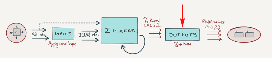
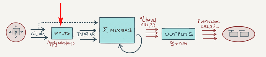
The graphic below illustrates the stages from source to output:
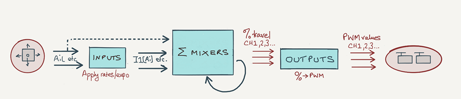
In the diagram:
- The sticks and knobs are Sources
- Inputs apply rates and expo
- Mixers apply mixes and generates channel values
- Outputs convert % channel values to PWM values
Let's now take a tour of each of these elements. A red arrow indicates where we are in the loop.
Sources
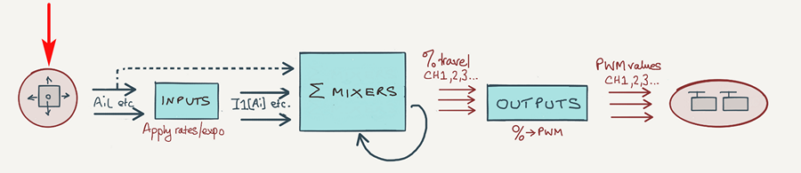
All computer programs need data to work with. With OpenTX, the data are your sticks, switches, inputs, trims and so on. The general term for these is sources. Each source has a unique ID, for example:
- elevator stick = Ele
- switch labelled 'A' = SA
- right slider = RS
- left potentiometer = S1
Each source carries a value between −100% and +100% according to its position. Zero represents the centre. Examples:
- Elevator stick forward -> Ele = 100 %
- Aileron stick 50% left -> Ail = -50%
- Switch SA down -> SA = 100%
- Left slider at centre -> LS = 0
These % values will be manipulated as they pass through the input, mixer and output stages, ending up as PWM values for positioning the servos.
Special sources
Before we leave the topic of sources, I'll mention a couple of special ones:
- Inputs: These are based on the transmitter controls but incorporate rate and expo. More later.
- 'MAX': The MAX source has a constant value of +100.
Note 2: Channels, Lua scripts and telemetry can also be used as sources, however they won't be discussed further here.
Mixers
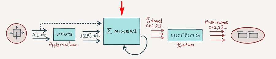
Mixers are central to OpenTX. In fact, there's only one kind of mixer and it's very simple to describe:
- A mixer represents ONE interaction between ONE source and ONE channel.
As you've guessed, there's not much you can do with a single mixer. However, by utilising multiple mixers in combination you can create highly sophisticated setups.
In general, each channel will be served by a stack of several mixers; each mixer makes an additive contribution to the channel. A complete setup may have anything from a couple to several dozens mixers, depending on complexity.
How to create a mix
To create a mix, go to the Mixers screen, select a target channel, and open the mixer editor.
The three key fields as follows:
- Source - stick, slider etc.
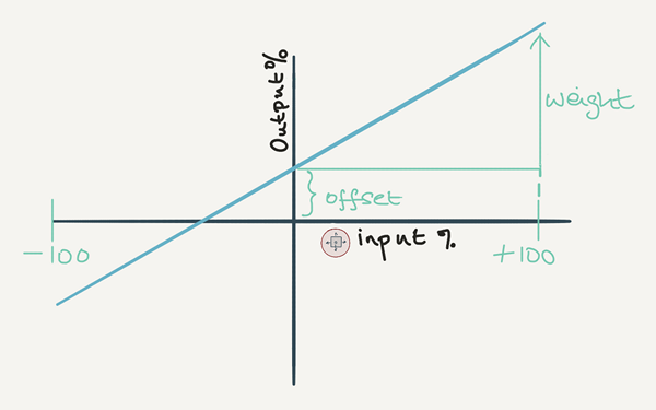
- weight - the rate or 'strength' of the mix
- offset - an offset, much like a trim offset
The mixer output is calculated as follows:
The mixer output represents % of available travel on the destination channel. (We'll see how to set available travel when covering the Outputs stage).
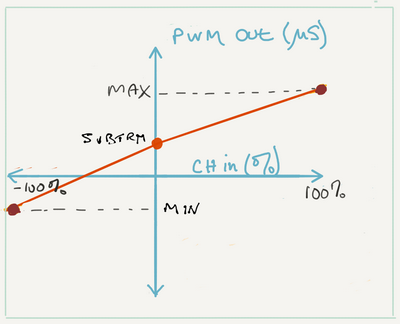
Shown as a graph of output v. input, weight is the slope, and offset is the output value for a zero input value:
Default mixer settings
The default weight and offset are 100% and 0% respectively, so output = input.
Three mixer scenarios
In this section, we'll look at three common mixer idioms which you'll use in your own setups:
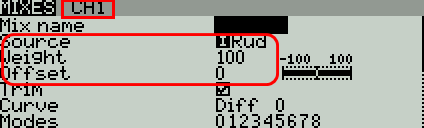
Mixing 1 source to 1 output
The screenshot below shows the simplest possible setup - just a single mix, with the aileron stick driving CH1. You can read the line as: "Channel 1 is affected by the aileron stick, with 100% effect":
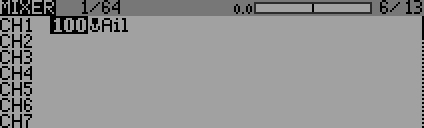
Try it - go to the Mixers menu, and create a mix for CH1. Set 'Ail' as the source and leave all the other options at their default values. As you move the aileron stick, the servo should respond. Now adjust the weight and offset, and observe the effect.
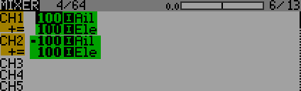
Mixing 1 source to multiple outputs (example: dual ailerons)
Models with ailerons normally have one servo driving each aileron. In terms of programming, it means defining two mixers, one for each channel. Each mix is driven by the aileron stick.
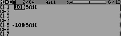
In the example below, CH1 and CH5 are the aileron channels. To indicate that the ailerons work in opposition, the sign of one of the mixer weights is reversed.
Mixing multiple sources to 1 output (examples: delta, V-tail)
In some cases we need more than one mixer to drive the same channel.
Take the example of a V-tail. Each half of the V-tail must move in response to (a) the rudder stick and (b) the elevator stick. So two mixes are needed for each half.
Here's the Mixers menu, showing the mixers for one of the V-tail surfaces (on CH5).
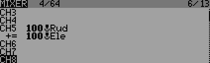
There will be a similar pair of mixers for the second half of the V-tail.
The mixer stack
The collection of mixers driving one channel is called the mixer 'stack' for that channel. Here are some rules which apply within a stack:
- Each mix in the stack makes an additive contribution to the channel.
- Mixers in a stack are independent of one another.
- The order of the mixers in the stack is not critical.
In the Mixers menu, mixers are displayed in channel order, so what you're looking at is a sequence of stacks. This makes it easy to see what's going on.
Channels
So far, we've made only brief mention of channels, so let's now dive a bit deeper. Note that the terms 'channels' and 'outputs' are often used interchangeably.
- 32 channels are available. As far as programming is concerned, all channels have equal status.
- Only the lower channels are actually transmitted (the precise number depends on the RF protocol). You will assign these channels to your servos and ESC.
- Higher channels can be used to help with programming. Don't worry about this for now (it's covered in cascading mixers).
The Outputs menu is where channels are managed. In the screenshot below, CH1, CH2 and CH3 have been given appropriate names:
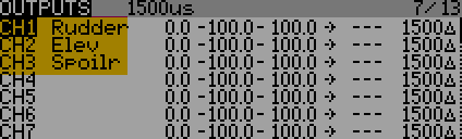
To the right of the Name column are the Subtrim, Min and Max parameters for setting the centre and end points. That's all we'll say about the Outputs for now - we'll revisit them later.
Designing your own mixing scheme
In this section, I'll describe a 4-step method of designing a mixing scheme. The same method can be used on any model regardless of complexity. Once you've tried it on one or two models, you'll find it easy to do it in your head.
Designing the mixers for a flying wing
We'll use the example of a simple flying wing. These normally have two elevons:
- The elevator stick dries the elevons in the same direction.
- The aileron stick drives elevons in opposing directions.
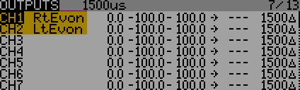
Step 1. Assign channels
The first step is to decide which channel goes with which servo. Then open the Outputs menu and type in the channel names. These names will help you identify the channels in other menus.
Step 2. Identify stick/servo interactions
Next is a thought exercise! Pretend that you're moving a stick, and make a list all the channels which are affected. Repeat for all the main controls used for this model (you can ignore the trims). Represent each interaction using the format source -> channel:
For our flying wing, the aileron stick ('Ail') has these interactions:
Ail -> CH1
−Ail -> CH2
Note the negative sign in CH2 to denote that the elevons are moving in opposite directions.
And the elevator stick:
Ele -> CH1
Ele -> CH2
No negative sign is needed, since the elevons move in the same direction.
Step 3: Convert interactions into mixer lines
Next, write the interactions in reverse:
CH1 <- Ail
CH2 <- −Ail
CH1 <- Ele
CH2 <- Ele
So now, each line reads as "[channel] is affected by [source]". This corresponds to the way mixers are entered into the Mixer menu.
Step 4: Enter mixer definitions
Finally, go to the Mixer menu. From your list of interactions, create a mix for each one. Set the weights to 100% - we'll see how to adjust this later. Note also that the negative aileron rate translates to a negative weight (−100%).
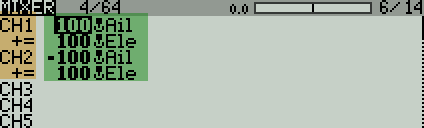
That's it, done!
There's just one shortcoming: we have assumed 100% rates for both the aileron and elevator sticks. We could reduce the travel by reducing the mixer weights, however this would require four adjustments: two in the aileron mixes, and two in the elevator mixes.
A much better way is to use inputs. Using inputs, there are just two adjustment points: one for the aileron input, and one for elevator input. We'll see how this is done in the next section.
Inputs
Inputs are based on regular sources, but include rates and expo. They are especially useful for dual ailerons, as they provide a single adjustment point for rates and expo. However, they should be used for all the main flight controls (ailerons, elevator and rudder).
Unlike raw sources, inputs are not built in - they must be created first.
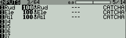
The Inputs menu shows a list of all the inputs which have been defined. Note that inputs are displayed with an '[I]' prefix, and raw sources are drawn with a stick icon. Read the first line as 'the rudder input is based on the rudder stick with 100% effect'
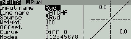
To create an input, select a blank line and open the editor. Then set an input name (max 3 characters), a source (stick, slider etc.), a weight, and optionally an expo value. The line name is optional.
AETR and channel order
Did I say you have to create your own inputs? Well conveniently, when you create a new model, OpenTX creates inputs for the main flight controls [I]Ail, [I]Ele, [I]Thr and [I]Rud. It also creates four mixers and populates the outputs. The default channel order is "AETR" ([I]Ail->CH1, [I]Ele->CH2 etc.)
You can change the default order in the Radio Setup menu.
Adding inputs to the flying wing
Using our flying wing example, we'll use the predefined [I]Ail and [I]Ele inputs. We'll assign a weight of 90% to the aileron input, and 30% for the elevator input. We'll set expo to 10% for both inputs.
The Inputs menu will look something like this:
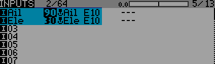
You can read the first line as meaning: "the aileron input ([I]Ail) is based on the aileron stick (Ail), with 90% effect, and 10% expo (E10)"
Next, we must go back and edit the mixers to use inputs instead of the raw sources we used previously:
The first line means: "Channel 1 (CH1) is based on the aileron input ([I]Ail) with 100% effect"
Note that I have set the mixer rates to 100%. This means "Use 100% of the rates in the inputs".
Now, in order to alter the aileron rate, we only need to alter one input weight, instead of two mixer weights. Same for the elevator.
Choosing between inputs and sticks.
When choosing the source of a mix, you don't have to use an input. It's only necessary if you need to adjust rates or expo. In other cases, just use the raw sources. Some guidelines:
- Use inputs for the main flight controls, for example rudder, elevator, aileron.
- Use the raw sources for controls such as motor, spoiler, crow. These don't normally require rates or expo.
Inputs are an important part of OpenTx, and you can read more about them here.
How commands are processed
In this section, you'll learn how your stick commands are processed. A good understanding is useful for troubleshooting your setups.
The first thing to remember is that weights are multiplied cumulatively as data flows from inputs to mixers to outputs.
Let's look at the flow of data with our flying wing. We'll consider just the inputs and mixers:
So now let's see how the stick values are processed.
Taking the inputs first, these act on the aileron stick position and apply a weight:
[I]Ail = Ail_Stick x 90%
[I]Ele = Ele_Stick x 30%
Next, the input values are aggregated in the Mixers:
CH1 = [I]Ail + [I]Ele
CH2 = -[I]AIl + [I]Ele
Expanding the input values::
CH1 = (Ail_Stick x 90%) + (Ele_Stick x 30%)
CH2 = (Ail_Stick x -90%) + (Ele_Stick x 30%)
Let's now apply these equations to calculate the channel values:
| Sticks | Channel values | ||
|---|---|---|---|
| Ail stick | Ele stick | CH1 | CH2 |
| (centre) 0 | (centre) 0 | 0 | 0 |
| (full right) 100% | (centre) 0 | 90+0=90 | -90+0=-90 |
| (full left) −100% | (centre) 0 | -90+0=-90 | 90+0=90 |
| (centre) 0 | (full forward) 100% | 0+30=30 | 0+30=30 |
| (half right) 50% | (half forward) 50% | 45+15=60 | -45+15=-30 |
| (full right) 100% | (full forward) 100% | 90+30=120 | -90+30=-60 |
Note that when the stick in the corner (full right/full forward), CH20 is 120% - that's 20% more than the available travel. In fact, channel values saturate at +/-100%. More accurately, channel values outside the range -100% to +100% are clipped on entry to the Output stage. More on that later, when we look at the Outputs stage.
The mixers monitor
Once you've designed your setup, you'll want to check the aggregated mixer values for each channel. You can do this using the Mixers monitor, which is available on the transmitter and in Companion.
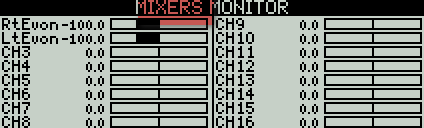
The values represent percentages of available travel. The actual travel is set later in the Outputs.
Tip: When designing your mixers, don't be concerned about the linkages or left/right imbalances - these will be dealt with later, when you calibrate the Outputs.
Mixers are the key to mastering OpenTx, and you can read more about them here.
Outputs
The Outputs stage is the final stage of processing prior to transmission. Its job is to generate PWM values ready for transmission. It is in effect a mapping layer - it maps aggregated mixer values for each channel into final PWM values. In effect, it allows you adjust your servo limits and centre.
The mapping can be thought of as two operations:
- Aggregated mixer values are clipped to +/- 100%
- A 3-point curve is applied, defined by Min, Max and Subtrim.
Let's look at each step in detail:
Step 1: clipping
As we saw earlier with the V-tail example, aggregated values can sometimes exceed +/-100%. Since +/-100% represents the limits of travel, the aggregated values are clipped to +/−100% before being passed to the Outputs.
Step 2: Min/Max/Subtrim applied
The second step is to convert the aggregated values (after clipping, if necessary) to PWM values. This is done according to Min, Max and Subtrim.
- Min defines the PWM value corresponding to an aggregated mixer value of −100%.
- Max defines the PWM value corresponding to +100%.
- Subtrim defines the PWM value corresponding to 0%
Since the incoming channel values have been clipped to +/−100%, Min and Max also represent hard limits - think of these as electronic end stops for your servos. Subtrim is normally adjusted so that your servos are correctly centred.
The Outputs menu
The Outputs menu is where you adjust Min, Max and Subtrim. Additional parameters are Direction, and Curve.
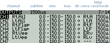
Curve is optional. If specified, it's applied after Min/Max/Subtrim. A curve can have between 2 and 17 points, so it offers more granular adjustment of the output response. It's particularly useful for calibrating flaps so that they track precisely.
The order of processing is:
- Min/Max/Subtrim
- Curve
- Direction
Channel % to PWM conversion
In the screenshot above, it'll be seen that Min, Max and Subtrim are shown as percentages, while they actually represent PWM values (yes, it's a little confusing!) The units are related as follows:
| Min/Max/Subtrim | PWM |
|---|---|
| -150% | 732 μs |
| −100% | 988 μs |
| 0% | 1500 μs |
| 100% | 2012 μs |
| 150% | 2268 μs |
PWM values outside the range 988 - 2012 μs are only available if Extended Limits is enabled in the Model menu.
Calibrating servo limits and centres
Calibration is the formal process of adjusting Min/Max/Subtrim. You can read more about calibration here.
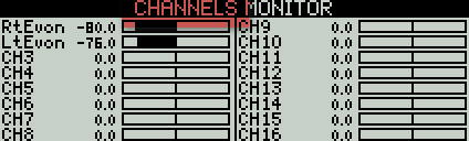
Channels monitor
You can monitor the final outputs using the Channels monitor.
Advanced topics
Mixer operators
We've seen how mixer line values are aggregated via addition. In fact OpenTx offers a lot more flexibility, by means of Multiply and Replace operators. The operator is specified in the Multiplex parameter:
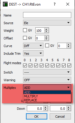
Okay, so let's see how these operators are applied.
At the start of the processing loop, the channel values for all channels are reset to zero. Next, the mixers are then processed in the order that they appear in the MIXERS menu.
As each mixer is processed, its associated channel is updated as follows:
- ADD - the mixer value is added to the channel value.
- REPL - the mixer value replaces the channel value.
- MULT - the channel value is multiplied by the mixer value, and the result becomes the new channel value
Note: if a mix is disabled, it's ignored entirely, as if it wasn't there at all.
The following examples illustrate the effect of the various operators. Note the importance of mixer order when using 'REPL' and 'MULT'!
Src = I1, op=ADD
Src = I2, op=ADD
result = I1 + I2
Src = I1, op=ADD
Src = I2, op=ADD
Src = I3, op=MULT
result = (I1 + I2) * I3
Src = I1, op=ADD
Src = I2, op=MULT
Src = I3, op=ADD
result = (I1 * I2) + I3
Src = I1, op=ADD
Src = I2, op=MULT (disabled)
Src = I3, op=ADD
result = I1 + I3
Src = I1, op=ADD
Src = I2, op=REPL
Src = I3, op=ADD
result = I2 + I3
Src = I1, op=ADD
Src = I2, op=REPL
Src = I3, op=MULT
result = I2 * I3
Src = I1, op=ADD (disabled)
result = 0
The 'MAX' source
MAX is a special source which doesn't correspond to a physical control. Instead, MAX supplies a fixed value of +100. In conjunction with weight, it can be used to simulate the effect of a fixed stick position.
Src = MAX, wt =100 -- output = 100%
Src = MAX, wt=50 -- output = 50%
Src = MAX, wt=−100 -- output = −100%
Here's a simple example, showing a crude motor arming system. The motor is armed when SA is down.
- The Thr line provides variable motor control via the throttle stick
- The MAX line provides a fixed value of −100 corresponding to motor off. The line becomes active when SA is not in the down position (the ! operator in !SA_down means 'not'). When it's active, it overrides the previous line (via the 'multiplex=REPLACE' parameter), and stops the motor.
CH7:motor
Src = Thr, wt=100%,
Src = MAX, wt=−100%, switch=!SA_down, multiplex = REPL
F3X sailplane mixer scheme
If you're familiar with F3X sailplanes, you may wish to look at interactions and mixes for F3X sailplanes. Such a scheme will normally be optimised by means of Inputs (described later in this article), GVARs and cascading mixers.