
Building the Calypso Contest V
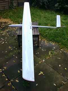 "Calypso Contest" is an F3B/F3F machine designed and manufactured by Stuart Blanchard.
The model is available in both T-tail and V-tail configurations with the latter the subject of this review.
Boil-in-the-bag?
All components arrived in a big strong carton with ply end plates. No chance of damage here, as the individual components came ready-packed in optional padded bags - four in all.
The fuselage bag has the handle positioned at the c.g. position - a nice touch.
Materials and construction
- Fuselage is epoxy glass with local kevlar reinforcement.
- The wing is a three-piece design, with a large centre section panel and smaller tip panels joined with substantial rectangular section carbon rods.
- Wing panels are hollow mouldings with composite glass/balsa/glass skins and carbon spars.
- V-tail halves are hollow glass mouldings, and are detachable from the fuselage. Each half slips over a short carbon rod permanently fixed to the fuselage
- Control surfaces are bottom-hinged, with accurately moulded shrouds.
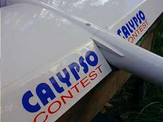
First impressions
The quality of the mouldings is quite astonishing - surface finish is superb, panel join tolerances are consistently measured in small fractions of a millimetre not just in a few critical areas, but throughout the airframe.
The result is that almost no rework is required - a considerable achievement by the manufacturer.
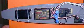
Choice of Radio
I decided to install my trusty Futaba system
- Futaba 7UGFS radio with PCM Rx
- 4 x Graupner 3341 servos in the wing
- 2 x Futaba 9601 servos in the fuselage
- 1200 maH 4-cell battery
Obviously the latest gear will provide more programming flexibility, but any F3F/F3B capable radio should be suitable. See Setting up your Futaba Super 7 for details on programming.
Installing wing servos
Space for the aileron servos is very tight. Not all 15mm servos are created equal, so as a first step make sure your servos will fit. Futaba 9601's are a bit over 15 mm. Graupner/JR 3341's are about 14.5 wide. Even with the 3341's some material may need to be shaved off the case.
Tips:
- There is more room for the flap servos so start with these.
- Mount the aileron servos as far forward as possible, otherwise they may project through the bottom skin.
- Mount them so they in contact with the top skin, for the same reason.
- Make sure you can mount the servos so they can be removed. It's perfectly possible to do this but requires planning.
A word about the mounting screws - grommets are not used, so mounting screws need to be threaded all the way up the shank. They will also need to be shortened - I used a cutting wheel on a mini drill to do this.
Assembling the Keel
The keel is a nicely finished balsa/glass sandwich with kevlar reinforcement. It's purpose is (a) to attach the radio gear, and (b) as an anchorage for the carbon ballast tubes.
Keel assembly is largely a question of drilling lots of holes in it. Some tips:
- When position the servos make sure the ballast tubes aren't obscured.
- Use the moulded scribe lines as a guide when drilling the pushrod exits, and ballast tube holes. They are pretty accurate.
I found it necessary to relieve just a little material from both the keel and the inside of the fuselage at the join. We're talking about very small amounts here. Be careful not to introduce a taper on the keel's flange. The keel needs to be a tight fit in the fus.
The keel is glued to the fus using cyano. ZAP CA is recommended. Whatever you use, make sure you fit the keel the right way up! This is an easy and very expensive mistake waiting to be made. No, I didn't make it, but my pulse rate went up when I realised I hadn't checked the orientation before gluing.
Wiring the wing
Easiest to rig if you use 9-pin D or 15-pin (preferred) VGA connectors between wing and fus. Some people glue the connectors in place, but there is very little spare depth in the fus so I just left my connectors floating.
I used ordinary extension leads for the aileron and flap servos. This is less neat than gluing connectors to the ribs either side of the panel break, but simpler to service and surely more reliable. I may go the high-tech route if the simple approach takes too long to rig.
There's a lot of wire floating around in the wing. Futaba should be OK as regards interference suppression - consult other users of your radio in case you need to take preventive measures.
Assembling the Towhook
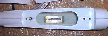
The towhook is soldered to a sliding brass plate which is fixed to a plate in the fuselage bottom via a single 4mm bolt. Slackening the bolt allow the hook to slide fore and aft.
Some tips:
- The fuselage plate is made from epoxy glass sheet. The only sheet I had was in the form of circuit board with copper on one side, so I stripped the copper with a sharp knife. Time consuming, but it works.
- The most difficult part of the process is bending the steel rod to make the hook! Best if you have access to a heavy gauge wire bender.
- Use a shakeproof washer under the 4mm nut to prevent the sliding plate from sliding under load.
Wing Joiners
Substantial section carbon joiners are used to attach the tip panels to the centre section. They were just a tad too tight for my liking so were relieved using wet and dry, easily accomplished in a few minutes.
Flap and aileron linkages
I thought doing the linkages would be tricky in the restricted space, but it turned out to be easy.
- For ailerons, set the servo arms perpendicular to the direction of travel at neutral.
- With the flap servos, the arms can be raked forward a little.
- Adjust the quicklinks to get as accurate a neutral as you can. Only use the radio for fine tuning.
After setting up linkages, the servo covers can be trimmed. I found a pair of tin snips perfect for this.
Setting up the radio
See Setting up your Futaba Super 7
Flying
Very easy to fly but not as fast as the Ellipse.
Update
Since I started this review, Stuart Blanchard has started to produce a new model the Calypso "Cobra". Features a pylon-mounted two piece wing. Contact Stuart for details.
Specs
| Span | 3000mm |
| Area | 60.8 dm2 |
| Aspect Ratio | 14.8 |
| Airfoil | RG15 |
| Tail plane Area |
T: 6.1 dm2 V: 7.5 dm2 |
| Airfoil | NACA 0009 |
| Weight | 2500 - 3400 g |
| Loading | 40 - 55g/dm2 |
| Controls | Rudder, Elevator Aileron, Flap, Crow brake |
Manufacturer
Model Technology