Calibration (CAL) Mode
Introduction
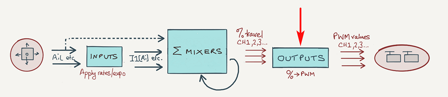
In this article, I will explain how to add a special 'CAL' mode to your setup, for calibrating the outputs. This will allow you to generate mixer values of -100%, +100% and 0% on demand.
Adding a CAL mode to your setup
CAL mode requries a special mix to be added to each servo channel. The mix simply passes the source value unchanged, so the output sees values of -100% to +100% with 0% at centre. The Multiplex option must be set to 'Replace', so all the mixes above the CAL mix are ignored.
Here's an example of a CAL mix for the elevator channel. The calibration is controlled using the elevator stick:
CH1:Elevator
[mix 1] ...
[mix 2] ...
[CAL mix] Src=Ele wt=100 Multiplex=REPL Trim=NO FlightMode=FM1:CAL
To perform the actual calibration:
- Ele stick back (−100) => adjust servo lower limit via Min
- Ele stick at centre (0) => adjust servo centre via Subtrim
- Ele stick forward (100) => adjust servo upper limit via Max
The CAL mix in detail
This section explains the special mix in more detail.
Setting up the CAL mixes
For each servo channel, add a mixer-line to the end of the mixer list:
- Mixer name = 'CAL'
- Source = [stick used for calibration, see below ]
- Weight = −100% or +100% (see below)
- Offset = 0
- Diff = 0
- Include Trim = No (bypass trims)
- Include DR/Expo = No (bypass rates)
- Flight mode = FM1 (optional, see below)
- Multiplex = 'REPL' (replaces all prior mixer lines above for that channel)
Source is the stick/pot/lever to drive the servo during calibration. It need not be the same as the flight control. Specify the raw control only, for example Ele, Ail (do not select inputs like [I1]Ail as these include rates and expo).
It's a good idea to move related surfaces using a single control, so you can equalise their responses by eye. For example, here's a typical scheme for a sailplane:
- Aileron stick -> calibrate left/right aileron servos
- Throttle stick -> calibrate left/right flap servos
- Elevator stick -> calibrate elevator servo (X-tail) or left/right V-tail servos (V-tail)
- Rudder stick -> calibrate rudder servo (X-tail only)
Activating the CAL mixes
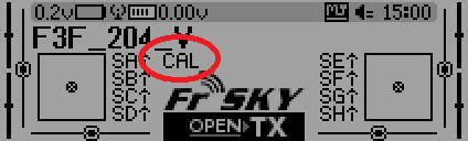
The CAL mixes may be activated directly via a switch, or indirectly via a dedicated flight mode.
The flight mode method has the advantage that the flight mode is displayed on the screen, but requires that you use FM1 (the highest priority mode), so that it's available on demand. If this is inconvenient (maybe you already have flight modes assigned), then the direct switch approach is fine.
Setting output direction
To make the calibration procedure consistent, set Direction in each output so that:
- A +ve change in Min, Max or Subtrim moves the control surface up or to the right.
- A -ve change in Min, Max, or Subtrim moves the surface down or to the left.
The easiest way is to try it. Go into the servos menu. Then for each servo adjust Subtrim back and forth, and see which way the control surface is moving. Reverse the output if necessary. Note that if an output is reversed, all the mixers affecting that output must also be reversed.
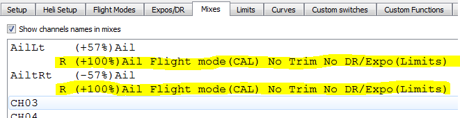
Example integration
Below is a screenshot from OpenTx Companion, showing two aileron channels and the extra CAL lines. The 'R' at the beginning denotes a REPL directive.
Demo file
Hardware calibration
For correct operation of your radio, remember that your sticks must also be properly calibrated as well! This is achieved via the OpenTx hardware calibration menu (Long press Menu -> Page x 8)