The box can be used to carry the completed model
Welcome to the printer-friendly version of R/C Soaring's
Ikarus Piccolo review.
R/C Soaring (UK) - http://rc-soar.com
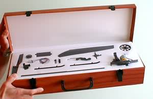
The kit comes in a lightweight plastic box which has a carrying handle and can be used to transport the completed model.
The kit comprises plastic and carbon components, and various small parts in numbered polythene bags. An excellent set of instructions is provided in English and German.
A nice touch is the inclusion of a tiny tube of CA adhesive, wet and dry paper and a set of small screwdrivers.
The box can be used to carry the completed model
Depending on your bundle, a Piccoboard , servos and nicad may be supplied with the kit. If not, these items are available separately. The Piccoboard is essential unless you really know what you're doing and are prepared to shop around for separate components.
Training landing gear is also available, consisting of five ping pong balls threaded on 2mm carbon rods. I found these very useful when learning to fly.
The Piccolo's head is based on Dieter Schluter's simplified Hiller head used in his early R/C helicopters way back in the 70's (the full-size Hiller head was patented for full size choppers in the early 50's).
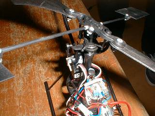 Hiller/Shluter head.
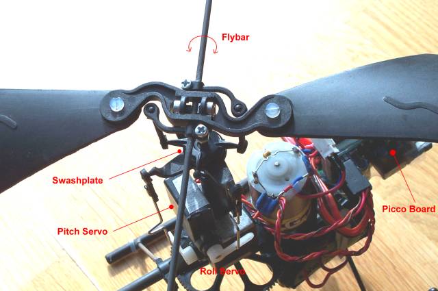
Note there are two sets of whirly things - the main rotor to which the
blades are attached, and a one-piece flybar with adjustable paddles at
each end. The flybar rotates
in a plane which tends to follow that of the swashplate - any
deviation causes a restorative force to be generated by differential
lift on the paddles.
The main rotor is influenced by the flybar, i.e. not controlled directly by the servos. This results in good stability and relatively low loads on the servos.
Rotor blades are fixed pitch, this makes aerodynamic balancing less critical than with collective pitch as well as simplifying the mechanics.
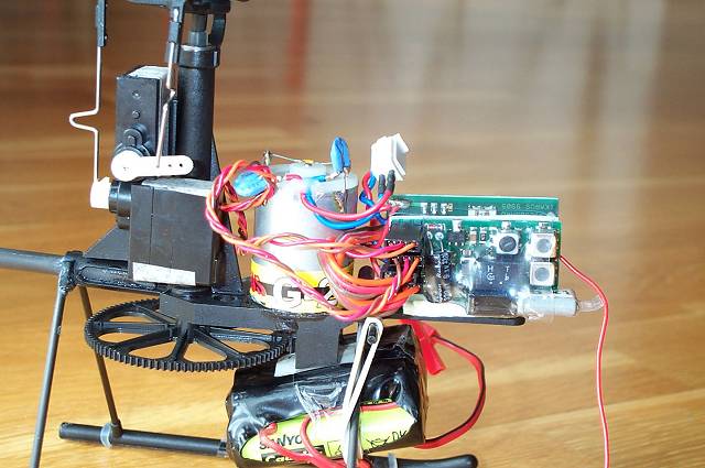
The Piccoboard is an amazing device containing the throttle / tail-rotor mixer, BEC, two speed controllers, and piezo gyro all in one small package.
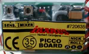
The Piccoboard. Pots are for tail gyro sensitivity and
throttle-to-tail-rotor mix.
The Piccoboard is usually supplied with a 4-function Rx on a second PC board. The two boards come stuck together with double sided tape and wrapped in heatshrink to form a complete unit.
The receiver is a 4-channel unit. Two of the receiver outputs go directly to the speed control inputs of the Piccoboard via short flying leads. The other two outputs are connected to the the pitch and roll servos.
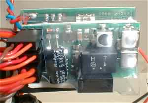
Receiver board showing Hitec/JR connectors. Xtal fits socket bottom
left.
Components are made mainly of glass filled plastic, with some carbon components e.g. tail boom and main skid supports. An excellent set of instructions is provided.
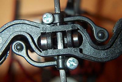
Rotor head detail. Note twin
ball bearings for paddle tilt.
There are 10 separate parts here.
Assembly is straight forward aided by the excellent fit of all parts. A few points:
Whatever gear you use, ATV and servo reversing are essential, and exponential is also useful. No mixing is required. Thus a mid-spec non-computer radio can be used.
I use my 10 year old Futaba FF7 Tx. I gave up using my Multiplex 3030 - the antenna is too long for comfort indoors and its extra programming flexibility offers no advantage for this model!
Assembly was completed in three evenings. When the last component was screwed in place, I connected up the battery, switched on the Tx and… disaster (well, almost)! The main rotors immediately spun up and I watched in horror as the Piccolo edged off the workbench with rotor blades flailing and then fell in a heap of ball joints on the workshop floor.
Well much to my amazement nothing broke – the ball links simply un-balled themselves. The main problem was finding the rotor bearings which had been flung to opposite ends of the workshop.
The cause was interference from a nearby fluorescent lamp. I learnt some useful safety lessons:
Before the first flight, take a few minutes to take stock of things and check your setup:
The swashplate must follow the stick, i.e. forward on the stick and the swashplate tips forward. The instructions are a bit vague about this, if you just follow your aerodynamic instincts without taking into account gyroscopic lag, your swashplate will end up 90 degrees out of phase. Been there, done that!
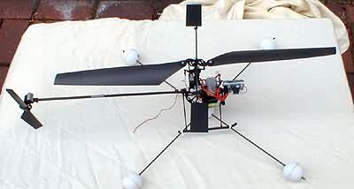
Note trainer gear - carbon rod and
ping balls. Canopy removed for first flights.
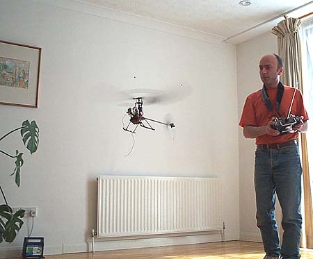
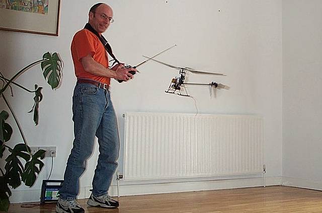
My living room offered a suitable space about 12 ft * 15 ft with a wooden floor, and I would not suggest anything much smaller than that. I spent the first "flights" just getting the trims and mixing right without lifting off. Gradually the model started scuttling around in ground effect, like a demented crab.
Fly, crash, re-adjust, fly etc. was the order of the day for the first several flights. However the model is remarkably tough, the main rotor just flies apart at the ball joints. Breakages are generally easily fixed with cyano. Incredible really given the amount of punishment it's received.
Gradually my flight times increased and confidence grew, and I can now fly the model quite comfortably in the living room including nose in, and slow 360-degree pirouettes in front of me.
Some tips:
During take off, get out of ground effect as quickly as you can. GE extends to about 1 ft clear air below the skids.
Once in the air, adjust the trims so you can take your fingers off the sticks for a second in the hover. If the model is nicely trimmed hands off, it's a lot easier to handle.
The Piccofly simulator is a very effective training aid which I strongly recommend for rookie chopper pilots (see my review of the Piccofly sim). With the sim I was able to practice nose-in and pirouettes without risking the model.
Having seen Clive Calef's beautifully smooth Piccolo in action at an indoor meet at Potters Bar, I realised my own Piccolo was vibrating excessively. I set about curing the imbalance and was amazed at the improvement. The smoothness allowed me to start doing nose-in flying in the living room.
The first stage is to find the source of the vibration. This can be done using a process of elimination:
To balance the main blades properly, you need to balance both statically and dynamically. The technique I adopted does not need weighing scales and although it is not perfectly accurate it made a worthwhile improvement.
The CG of the two blades combined must lie at the centre of the hub in order to balance out centrifugal forces.
Dynamic balancing requires CG of the blades to match each other. Dynamic balance ensures that when the blades bend upwards under load, the centrifugal force of each blade is acting at the same vertical position on the rotor shaft.
Adjustment of Dynamic balance will affect static balance, so you will need to repeat each set of adjustments.
On my unit there is a distortion in the rotor head moulding which means that the angle of attack of one blades is about three degrees out. This came as some surprise! Check yours by laying a straight edge under the blade mounting pad, and see if it lines up with the flybar. If not, shim up at the hub as necessary.
If after all the above have been checked and there is still excessive vibration, check that the tracking is not grossly out. Place pieces of tape of different colours on each tip to identify the "high" blade.
This is an add-on pack from Ikarus. The kit contains:
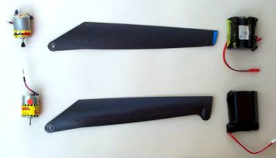
Old above, new below
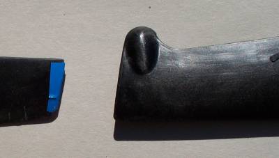
Tip detail, old left new right. I'd be interested to know how they came up with
the "pod" tip shape!
The new blades have identical span, section and planform as the old. However, they appear to be a little stiffer both in torsion and bending - perhaps a slight change in the composition of the plastic. The only visual difference is the pod on the tip. As it is solid and has no obvious aerdynamic function, my guess is that it tweaks the CG of the blade but I can't be sure.
The blades and motor are a simple drop-in replacement for the original parts, and took all of 10 minutes to install.
The motor comes with a sheet advising that because of the brush design, it should be run in one direction only - no problem as it's already supplied with the usual polarised plug. Running in should be done at 1/8 throttle with no load. At least that's what my limited German told me, and I followed my instincts!
Ikarus supply 8,9 and 10 tooth pinions with the new motor. The new pack is 8 x AAA cells, 550mAH. Although there was no label on my pack, it behaves like an NiMH pack with a slow decline in power into ground effect.
I've had just three flights as I write this, so this is just a preliminary assessment. The flights were indoors. I used the original 7-cell pack with the 9-tooth pinion. First impressions are that it flies more smoothly but is maybe a little less responsive.
Part of the flight involved my usual journey from the television to the coffee table at the other end of the room. Forward flying is easier, the porpoising is much reduced.
I tried some nose-in flight but I didn't feel very comfortable doing this yet - the Tx settings for roll and pitch really need to be adjusted. I'll be doing this in subsequent flights.
I wasn't timing the flights so it's not possible to assess the effect of the new components.
All in all quite promising, but further evaluation is required. Stay tuned!
24 May 2001 The new motor is causing the speed controller to shut down after a minute or so. Either that or the motor itself is faulty. I proved this by changing the motor for the old one and that works fine.
So now I'm using the old motor and old battery pack with the new blades. This is allowing me to assess the effect of the new blades on their own. My conclusion is that the flight path is indeed smoother, but the model is slightly less responsive. Is this to be expected from the different weight distribution of the new blades? My guess is that outdoor flying will be easier with these blades.
25 May 2001 Suddenly the new motor is running well again. Increased the throws and the handling is improved. I'm getting used to the new blades! Sustained nose-in no longer a problem. All we need now is a nice calm day to try some flying outdoors.
5 June 2001 Successful flight out of doors.
With the Ikarus-supplied 7-cell 250 mAH Sanyo NiCd pack I get about 4 minutes per charge. I use a Robbe Infinity 2 charger, this is an excellent unit. On the Auto setting, it takes about 20 minutes to fully charge. With two packs you can fly on one pack while charging the other.
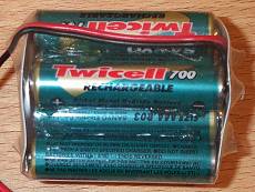 As of April 2001, I've made up an 8-cell Sanyo
Twicell 700 mAh NiMH pack. Flight times in the order of 7-8 minutes + 1
min ground effect. When charging NiMH, I set the delta peak
detection to Sensitive and disconnect
immediately after full charge is reached (conventional wisdom is that NiMH don't like
any kind of overcharging, including trickle charge).
As of April 2001, I've made up an 8-cell Sanyo
Twicell 700 mAh NiMH pack. Flight times in the order of 7-8 minutes + 1
min ground effect. When charging NiMH, I set the delta peak
detection to Sensitive and disconnect
immediately after full charge is reached (conventional wisdom is that NiMH don't like
any kind of overcharging, including trickle charge).
More recently still, I've started setting the charge current manually, to 700 mA, still with peak detection, this also works well. Interestingly, even on the manual setting, the Infinity still goes through a routine of ramping up the current from zero to 700 mA every couple of minutes, so even on the manual setting it appear to be doing some clever monitoring.
The model is remarkably resistant to crashes, but inevitably things break or wear out. Different folks seem to have different things go wrong, here's a list of things that I've had to deal with.
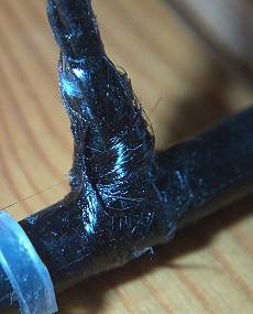 My landing gear struts tend to break at
the base. I use carbon tows to strengthen the joint.
My landing gear struts tend to break at
the base. I use carbon tows to strengthen the joint.
Get a few tows about 2" long, spot glue one end to the strut, wind the other end round the skid, and spot to the other side of the strut. Then apply cyano, wait to dry and cut off the excess carbon.
Very effective. (I got the idea from another page, can't remember but thanks to the author anyway!).
These tend to fly off all over the place and are difficult to find. I carefully cyano the bearings to the hub, this helps but occasionally the bearings slip off again, possibly because there's a film of oil on the inside of the bearings. I'd rather leave the oil on and put up with the occasional hassle.
Here's a mod which has saved me a lot of grief.
Instead of gluing the boom to the main and tail rotor assemblies, I now rely solely on a friction fit. This has two major benefits (a) it allows the tail rotor assembly to twist in the event of a crash, absorbing some of the impact energy and reducing the risk of damage to the boom. (b) the boom can be replaced very quickly if necessary.
Cracks in the boom are best fixed with slow-setting cyano, rubbed into the damaged area. I gave up using using low viscosity cyano, as it goes all over the place including the inside of the boom where it can end up playing havoc with the tail rotor motor power cable, or worse it can even dribble down the boom onto main rotor assembly, as I've discovered!
The plastic motor pinions tend to start slipping after a while. To prolong the period between re-gluing, roughen the shaft first with wet/dry paper. I use slow setting cyano to hold the pinion in place.
 At Dortmund Ikarus were supplying replacements which
had metal pinions, I bought one and have had no trouble. The problem
will be transferring the pinion to another motor when this one wears
out...
At Dortmund Ikarus were supplying replacements which
had metal pinions, I bought one and have had no trouble. The problem
will be transferring the pinion to another motor when this one wears
out...
Thanks to Kris Manbeck for this tip:
To remove the brass pinion for use on other motors, use a high powered soldering gun (about 100w), and a small vice. Put the motor in the vice snug. Next heat the (brass) gear with the soldering gun. While the gear is hot use a small pair of needle nose pliers or a small flat screw driver and simply pry it off of the shaft. Be carefull not to scar the teeth. If you use pliers try to stay on the hub of the gear. for install on the new motor. Freeze the new motor for a couple of hours (do not drop it after it is frozen the glue for the magnets gets brittle and the end bell is plastic they may crack on impact). Next heat the gear again with the soldering gun, after the motor is good and frozen! Hold the motor in hand or gloves. Do not use the vice. After the gear is hot lay it on something that will not melt! Face down (hub toward the motor) and press the motor on the gear. with the motor frozen (contracted) and the gear hot (expanded) they should slip together relatively easy. If it does not seem to work, do not pound the gear on! It may damage the brushes or end bell as they are delicate. Let the whole assembly set until cooled and thawed. ALSO be carefull not to push the gear on to far it will rub the motor can and MAY cause the washers inside to chew up the brushes if it pulls the armature to far out. If the gear slips on too far, quickly pull it out until it is free of the motor can, keep your pliers handy while you attempt this.
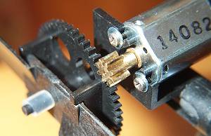
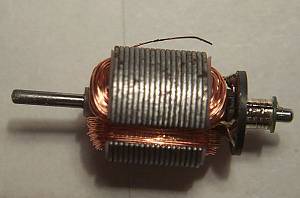 On
one occasion I found the tail rotor motor did not appear to be working
properly. I
dismantled it and found that one of the windings had broken at a solder
joint and had wedged itself
between the armature and the magnet.
The photo shows the damage. Note also the brush tracks on the
commutator.
On
one occasion I found the tail rotor motor did not appear to be working
properly. I
dismantled it and found that one of the windings had broken at a solder
joint and had wedged itself
between the armature and the magnet.
The photo shows the damage. Note also the brush tracks on the
commutator.
As an aside, disassembling the motor is easy, but putting it together again is another matter. The brushes are very delicate. If the end bell becomes separated from the armature you may as well toss the motor in the bin.
The Piccolo Fun looks identical to the Eco Piccolo, and they both share the same mouldings However under the surface you'll find some changes which reflect its budget status. The original ball bearings are gone in favour of cheaper nylon bearings, and instead of steel the main and tail rotor shafts are made of carbon. This means that the weight is slightly increased.
The canopy is pre-moulded in one piece from a Depron-like material and is noticeably heavier than the original.
One useful improvement is the adoption of a much more rigid anti-rotation collar.
In order to increase running time, I purchased a 3-cell 10.8 V Li Ion pack and a dedicated charger. Note these are not Ikarus items, they are distributed by J. Perkins and are badged "Enjoy Models".
On connecting to a car battery, the charger LED behaved erratically, and the battery appeared not to be accepting charge, so I returned both the charger and battery pack to Galaxy Models. Galaxy forwarded them to Perkins. 3 weeks passed and no word. I was then informed that the Perkins engineer was on holiday, at which point Galaxy sent me new units ex-stock.
However, the new unit was giving similar problems - the battery was still not accepting any charge!
Two bad chargers on the trot - this was more than a coincidence! Time to do some investigation.
If all else fails, read the flipping manual. Lo and behold that cigarette lighter plug is completely misleading - the minimum input voltage to the charger is 15 V! A phone call to the Perkins engineer confirmed the diagnosis of insufficient input voltage. One does wonder why the charger is provided with a car cigarette lighter plug.
Fortunately, I had a solution in the form of an old DC adapter, rated 15V / 1Amp. Using this, the charger works perfectly, and I'm getting around 18 minutes flight time per charge. The battery performance is fine and I'm very pleased with the combination of Piccolo Fun and LiIon.
The Piccolo Fun works well and is good value.
As for the LiIon battery and charger, if you have a suitable voltage adapter, the charger is OK. However, the ambiguity over the charger's voltage requirements needs to be sorted out before this charger can be fully recommended. It may be worth spending a bit more on something designed to operate off 12V, like the a Schulze Chameleon.
3 photos - 100KB
Ready to go
The front bit
Main rotor
| Al's Hobbies (suppliers, mail order) | http://www.alshobbies.com |
| Piccolo tips by Paul Goelz | http://www.pgoelz.com/ |
| Ikarus | http://www.ikarus-modellbau.de |