
Spektrum DX7 Programming Notes
Introduction and brief review
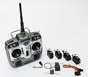 The Spektrum DX7 is the first full-range 2.4 GHz radio control system for R/C modellers. I reviewed it in the April issue of RCMW, and found it to be a well featured system (if not quite as flexible as some other 7-channel radios). It is nicely constructed, and provides a rock solid radio link.
Downsides are the poor balance of the box, rather archaic programming (though by no means worse than some other Far Eastern radios), and the need to install two receivers in the model.
The spread spectrum data link is very robust however, and as a result the set has become very popular here in the UK.
Here are some programming notes which owners may find useful.
- Programming four-servo wings
- Throttle 'kill' function
- other information.
Programming 4-Servo Wings
The increasing popularity of 3D electric models and F3x sailplanes has made support for four-servo wings almost essential in mid-range radios. While the stock mixers on the DX-7 only support two servos, the other two servos can be driven by means of a couple of PMIX's and a bit of effort.
So, let's see how to implement a basic 4-servo setup to support the following:
- 4-servo Aileron
- 4-servo Camber
- 4-servo Snapflap
STEP 1: Configure Flapperons
in the System menu, set the model type to ACRO, and the wing type to Flapperon (and optionally enable the V-tail mixer).
STEP 2: Connect the Servos
The table below shows the servo assignments. The wing servos are shown in purple - chs 2 and 6 are assigned to the inner surfaces ('flaps'), while chs 5 and 7 are assigned to the outer surfaces ('ailerons').
| Rx Channel | Connect this Servo | |
| 1 | THRO | Throttle |
| 2 | AILE | Right Inner |
| 3 | ELE | Elevator |
| 4 | RUDD | Rudder |
| 5 | GEAR | Left Outer |
| 6 | FLAP | Left Inner |
| 7 | AUX2 | Right Outer |
STEP 3: Disable the 'Gear' switch
The Gear function must be disabled, so it doesn't affect channel 5.
- Enter the SERVO TRAVEL menu
- Set the servo travel for 'Gear' to zero/zero.
STEP 4: Configure Flap system
The DX-7 provides a choice of activation method for flaps. The 'System' option will suit most sailplane pilots. It provides a choice of three flap presets, selectable via the flight-mode switch.
- Enter the SYSTEM->INPUT SELECT menu.
- Select 'system'.
- Set FLAP TRIM=INH
STEP 5: Configure the mixers
In the final step, we'll set up the stock mixers for the inner surfaces, with PMIX's for the outer.
| Function | Mixer Menu | Rate | Offset |
| Inner Snapflap | [ELEV->FLAP] | D=0/U=+10 | n/a |
| Inner Camber | [FLAP SYS] | NORM=0 MID=10 LAND=15 |
|
| Inner Aileron | [D/R] (to set travel) | ||
| Outer Snapflap | [PMIX3]: Elev->Gear | 0/+10 | 0 |
| [PMIX4]: Elev->Aux2 | 0/+10 | 0 | |
| Outer Camber | [PMIX1]: Flap->Gear | +100/+100 | 0 |
| [PMIX2]: Flap->Aux2 | +100/+100 | 0 | |
| Outer Aileron | [PMIX5]: Aile->Gear | +100/+100 | 0 |
| [PMIX6]: Aile->Aux2 | -100/-100 | 0 |
Notes
- PMIX5/6 must be used for the outer-aileron mix in order for the aileron trim lever to work.
- Aileron travel is set in two places:
- Dual Rate. This adjustment affects all four servos.
- PMIX5/6. This adjustment affects outer surfaces only.
- Differential is adjusted differently for inner and outer surfaces:
- For inner surfaces, use the Diff menu.
- For the outer surfaces, set different up/down rates in PMIX-5 and PMIX-6.
Crow Mixing
Owners of F3B/F/J sailplanes will be wondering whether the DX-7 can be used for crow brakes. Well yes it can, but the programming is tricky. Actually it's actually pretty horrible especially if you're used to the flexibility of a Multiplex radio as I am.
The main problems are:
- insufficient PMIX's to support crow mixing in addition to the basic mixing described above. As a result, two of the mixes above have to be dropped.
- the unpredictable effect of the Offset parameter in the Throttle mixes. This makes it tricky to set the crow travel accurately on the outer surfaces (it's easy enough on the inner flaps).
Nevertheless, here's my solution for crow. In order to free up PMIX's for crow, I've dropped two of the mixes, namely snapflap and camber on the outer surfaces.
| Function | Ch | Mixer Menu | Rate | Offset |
| Inner Snapflap | [ELEV->FLAP] | D=0/U=+10 | n/a | |
| Inner Camber | [FLAP SYS] | NORM=0 MID=10 LAND=15 |
||
| Inner Aileron | [D/R] (to set travel) | |||
| Inner Crow | [PMIX3]: Thro->Flap | +50/+50 | +100 | |
| Outer Crow | [PMIX1]: Thro->Gear | +50/+50 | -100 | |
| [PMIX2]: Thro->Aux2 | +50/+50 | -100 | ||
| Crow/Elev Compensation | [PMIX4]: Thro->Elev | 0/+25 | 0 | |
| Outer Aileron | [PMIX5]: Aile->Aux2 | +100/+100 | 0 | |
| [PMIX6]: Aile->Gear | -100/-100 | 0 |
Summary
We've seen how it is possible to program a basic 4-servo wing up quite easily if you don't need crow brakes.
Crow brakes are possible but with some compromises and difficulties.
It's worth remembering that the DX-7 also lacks flight modes and curves, and there may be installation issues arising from the twin receivers. While some modellers get around the latter by using the AR6100 park-fly receiver, this practice is not recommended for full-range applications.
Implementing a Throttle Kill function
There is no throttle kill function provided with the DX-7, instead there's 'Throttle Idle Recovery'.
For those who prefer a traditional Kill function, here's a solution which works off the MIX switch:
- Use PMIX-5 or PMIX-6
- mix THRO->THRO
- SW=MIX
- Rate = -100 / -100 (note both negative)
- Offset = -125 (note negative)
Note 1: use only PMIX-5 or 6, otherwise the kill setting will vary with idle trim.
Note 2: The kill position is adjusted via Offset.
Channel Assignments
Table below shows channel assignments of the DX-7.
| Wing Type | |||||
| Ch # | Normal | Flapperon | V-tail | Delta | Notes |
| 1 | Throttle | ||||
| 2 | Aileron | Flapperon | Elevon | ||
| 3 | Elevator | Vtail | Elevon | ||
| 4 | Rudder | Vtail | |||
| 5 | Gear | ||||
| 6 | FLAP | Flapperon | labeled as 'AUX1' on AR7000 | ||
| 7 | AUX2 | ||||
Mixing Architecture
The mixing architecture is quite simple.
Mixers: Simple case
Consider a mixer C1 -> C2, e.g. THRO -> ELEV
In the simple case (e.g. for Normal wing type), moving stick C1 will effect just the channel corresponding to C2. So with THRO -> ELEV mixer, moving the throttle stick will modify the signal to servo #3 .
Mixer: special cases
Things are only a little more complicated for the special wing types. Again, consider a mixer C1->C2. The table below shows the effect of different C2 and wing types:
| Wing Type | C2 | Output Channels | Relative sense |
| Flapperon | AILE | #5, #6 | opposite sense |
| FLAP | #5, #6 | same sense | |
| Delta | AILE | #2, #3 | opposite |
| ELEV | #2, #3 | same | |
| V-tail | RUDD | #3, #4 | opposite |
| ELEV | #3, #4 | same |
Examples for wing type = Flapperon
- Rudd -> Aileron
- Here, C2= Aileron, so the mix drivers flapperons in opposite directions (i.e. as ailerons).
Possible applications include:
1. Coupling of ailerons to rudder, where the rudder is the primary turn control.
2. Roll correction during knife edge.
- Elev -> Flap
- Here, C2=Flap. Displacing the elevator stick causes flapperons to move in the same direction. Use this to implement 'snapflap'.
Pulse Widths
Measured on aileron channel, trim at centre, all settings at default values (measured using servosim).
| Servo Travel | Min (mS) | Max (mS) |
| +50/+50 | 1.3 | 1.7 |
| +100/+100 | 1.1 | 1.9 |
| +125/+125 | 1.0 | 2.0 |
| +150/+150 | 0.9 | 2.1 |
Interestingly, the DX-7 outputs eight (not seven) channels at the DSC interface.