
X-Plane: a Model for Dynamic Soaring
In this article Craig Toutolmin describes his X-Plane project. Craig was the first to top 200 mph, and has his own unique approach to design and construction.
Main Components
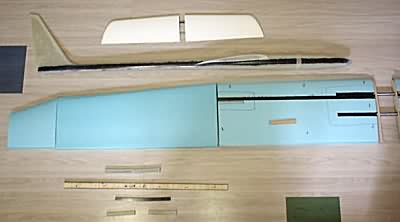
These are the basic parts of this "kit".
- The upper left are hollow mold stabs from Mickey Crawley.
- The Fuse is a Stilletto RG-15 from Jerry Slates at Viking Models.
- The cores are triple taper RG-15 cut by Tom Feldvebel - inner panel is high load 60.
- The tip joiners are 4 deg carbon pre-preg from Mickey Crawley.
- The spar is 1/2" engrain balsa with four plies of 4.8 oz uni carbon on the upper and two plies on the lower.
Tip Panel Preparation
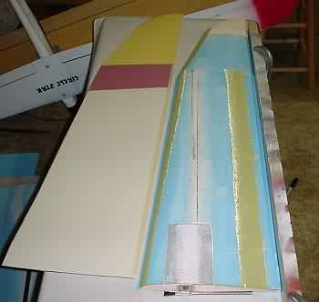 Same construction as center panel (1/2" endgrain, 4 plies 4.7 uni-carbon upper two lower).
The spar is on the mean 1/4 chord line to minimize twisting in flight.
There is a patch of 10 oz s-glass covering the joiner box top and bottom.
Kevlar leading edge wrap and hinge. 1/8" ply root rib.
Shaped balsa tip.
The mylars are waxed painted and hinged - ready to go.
Bagging the Tip Panel
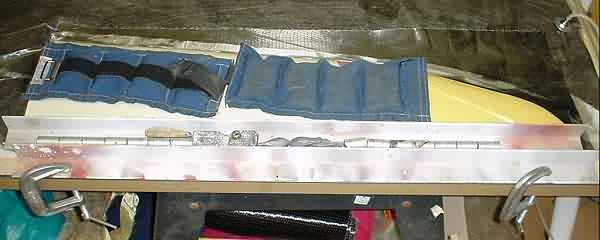
Its a confusing photo at first, so I'll explain. You are looking at the upper right tip panel with the trailing edge towards you.
I use a piece of aluminum angle clamped to the table to control the trailing edge in the horizontal plane. The bottom shuck is placed below the bag and butted up to the angle. After the wing has been positioned properly and pulled down twice with vacuum (15" hg), I add the second piece of angle to the top of the trailing edge and weight it down. This produces a pretty nice trailing edge.
Lay-up:
- one ply 4.7 oz uni-carbon (mainly to ensure carbon on the control surfaces and to make the bottom of the wing look cool)
- one ply 3.7 oz s-glass on a 45 deg bias (torsional workhorse)
- one ply 1.4 oz e-glass veil
 The major difference in the lay-up scheme between this and my last plane is that this plane uses a super strong spar to take the bending loads instead of a bunch of carbon on the skins. The skin handles the twisting loads. This is cheaper, stronger and more accurate. It is also more work. But hey, I have more time than money.
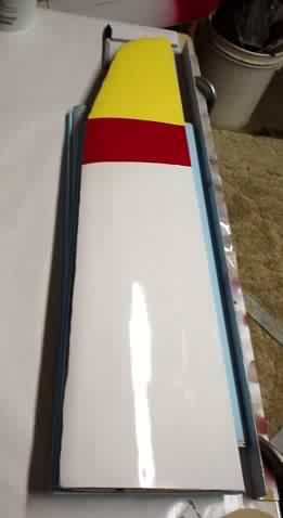
Photo shows the tip panel out of the bag with the flashing removed.
The Joiner System
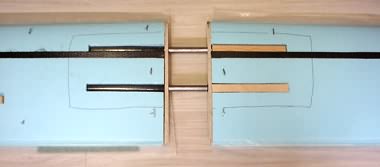 Here is the most important part of this plane. The wing joiner system at the root takes the brunt of the loads while DSing.
Ideally the wing would have been a three piece, but with the comercially available fuses I went with a four piece.
The joiners are 4130 seamless alloy steel (chromoly) MIL-T-6736 normalized. Tensile strength 90,000 psi. I used 1/2" diameter with a .125" wall. The joiners are 12" long.
The wing and fuse are fitted with carbon tube sleeves. The choice of chromoly over carbon was due to carbons flexibility and ability to break. This system will bend and not catastrophically break. The root ribs are 1/4" plywood. I used 1/2" x 1/8" spruce to cover the joiner tubes. Epoxy and microballoons fill the void/transition from the round surface of the joiner tube to the wing surface. The black lines on the cores show where the 10 oz s-glass patches will be placed.
Design Docs
Click here to download craig.zip (83kb). Contains Excel 97 workbook with the following:
- Design block for Plane Geometry
- Measure block for Plane Geometry.
- John Hazel's Lift and Cl calculator for triple taper wings.
Note one data point in the Measure Block is incorrect. The weight should be 8lbs-8oz not 8 lbs. Secondly, the fuse measurements do have the dimensions of the Stilletto fuse. The note that it is a Calypso fuse or whatever is from a block that I had input the data over.
Editors Note:
- All formulae in Plane Geometry worksheets are replaced with calculated values.
- For R/C Soaring's review of Plane Geometry click here...