Happiness is... sunshine, a model, and an X20!
Key concepts of Ethos
Introduction
Ethos is a wonderfully flexible operating system, however if you've come from another brand it may seem a little strange at first - even though it's quite simple. My aim with this article is to explain how Ethos works, and to give you the knowledge needed to design your own setups from scratch. So let's get started…
Overview
Central to Ethos, as in other R/C operating systems, is a sequence of steps repeated several times a second - that's fast enough to make your servos respond smoothly. During each cycle, Ethos reads the stick positions and converts them into channel commands. These are then sent to the RF module for transmission.
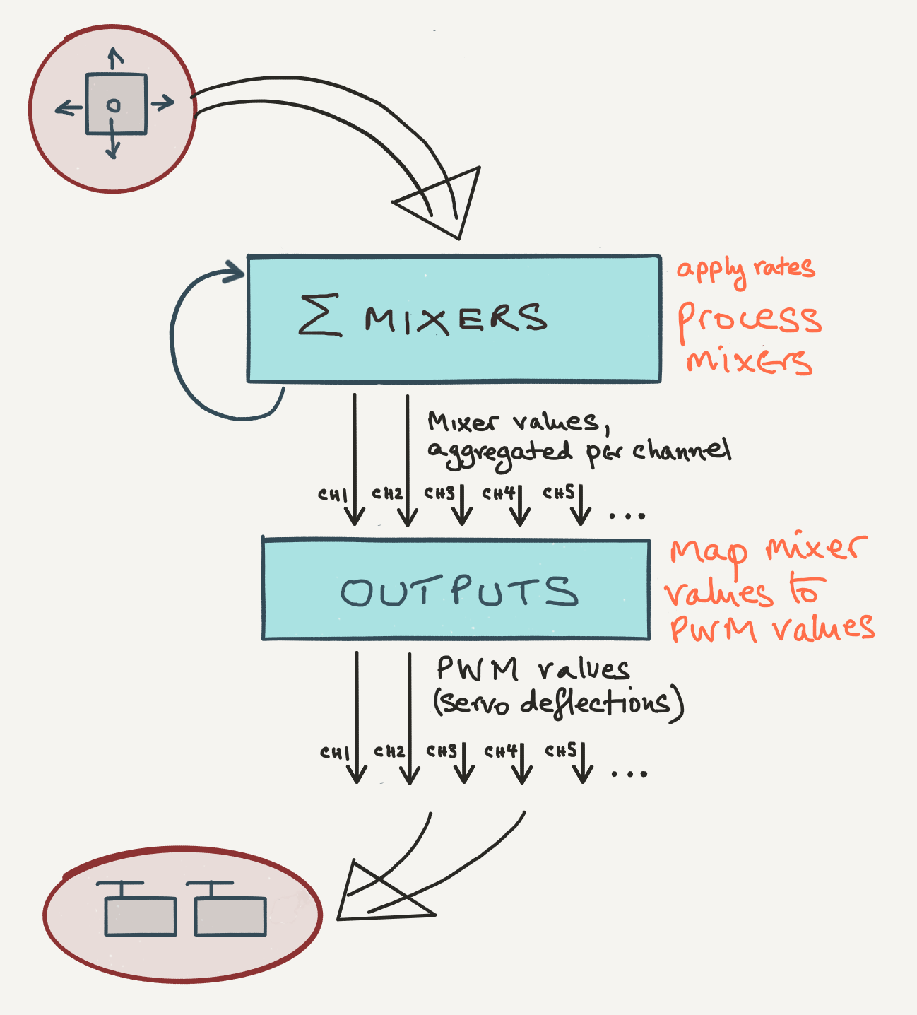
The graphic below shows the main processes:
The processing loop
There are two key processes going on:
- The Mixers layer reads the stick positions and applies any mixing. This layer is where you define the control logic.
- The Outputs stage is where adjustments are made to servo centre and limits. This layer is where you account for linkage geometry.
The ability to consider control logic and geometry separately is one of the great strengths of Ethos. Don't worry if this doesn't make much sense yet - it will 'click' when you start to program your models.
Channels
Ethos provides 64 general purpose channels. All channels may be programmed the same way, however only the lower ones are sent to the RF module for transmission. Channels which are not transmitted (so-called 'high' channels) can be used as helper channels (how this is done is beyond the scope of this introduction).
When you create a new model using the wizard, Ethos assigns the lower channels first.
Introduction to mixers
Ethos offers a number of predefined mixes as well as a powerful free mix. All mixers follow a simple convention:
A mix has exactly one (1) input source, and one or more (>=1) outputs.
Within a mix, the input will typically be subject to the following operations
- curve
- weight
- offset
The result is sent to the outputs. There are however variations to this rule, depending on the particular mix used.
The free mix is a special case, in that the internal operations may be freely defined by the user.
Mixer input sources
The source of a mix is normally a stick, slider or knob. Each source has a unique identifier, for example:
- elevator stick = 'Elevator'
- switch SA = 'SA'
- right slider = 'Slider right'
Each source carries a value between -100 and 100 according to its position. Taking a stick as an example:
- Stick centre = 0%
- Stick half down/right = +50%
- Stick full back/left = -100%
- Switch (e.g. SA) up position = -100%
- Switch down = +100%
- Switch centre = 0%
There are also a group of system sources, the most commonly used being MIN and MAX for emulating stick limits:
- MIN = −100%
- MAX = +100%
Finally, a mixer source can be another mix. This offers a mechanism for chaining mixers.
Choosing a source
Every mix has a single source associated.
With some mixers, for example the 'Ailerons', 'Rudders', and 'Elevators' mixers, the source is predefined. With other mixers, you choose the source. So for example with a Butterfly (crow) mix you could use a slider, stick, switch etc.
The same source may active in multiple mixers. For example, the aileron stick is a source which is common to the 'Ailerons' and 'Ail=>Flap' mixers, and both may be active simultaneously.
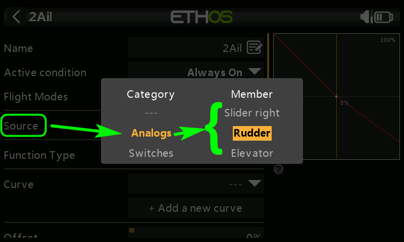
Choosing a mixer source
For more info, see the mixers page on this site.
Mixer outputs
A mixer gets the value of its source, transforms it, and sends the result to one or more outputs. Each output is associated with a numbered channels in the range 1 - 64. Only the lower channels are actually transmitted (the exact number will dependi on the RF protocol being used).
Some mixers offer a variable number of outputs. For example on a flying wing, you would use the 'Elevators' mixer and specify two outputs, one for each elevon channel.
A channel may be driven by more than one mix. For example, a flap channel may be driven by a Camber mix, and an Ail=>Flap mix. Each mix makes an additive contribution to its output channels.
Output values
While source values represent stick positions, mixer outputs represent percentage of available travel. So 0% represents the centre position, -100% represents one end point, and +100% is the other end point, for that channel. We'll see later how these quantities are mapped to PWM values representing actual servo positions.
How trims are handled
For the primary mixers (Ailerons, Elevators and Rudders mixers), the trims are included in the input. For all other mixers, trim values are not included included in the input - even if the source is an aileron, rudder etc. stick.
A trim can itself be a source of a mix, just like a stick. This offers some interesting possibilities. For example, if your setup is not using a particular primary mix, you can repurpose its trim to control something else.
Mixer processing
So far we've considered a mixer as a black box, with an input and one or more outputs. In this section we'll take a quick peek at what goes on inside.
In the simplest case, the mixer output value is calculated from the source according to, curve, weight and offset parameters. The order of processing is Curve, Weight and Offset.
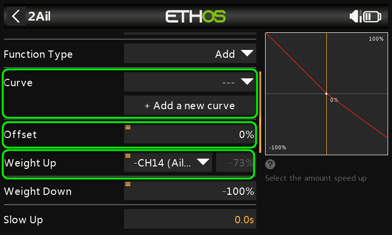
Mixer parameters
Mixer viewing options
By default, the mixer list shows mixers in the order in which they were inserted.
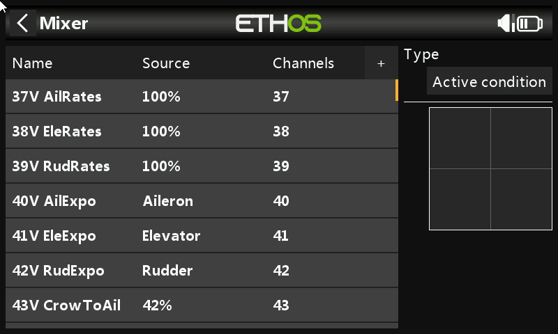
Mixes screen, normal view
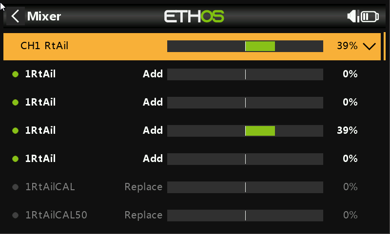
Mixes screen, stack view showing mixers for CH1
Creating your own mixers
Often you'll want to extend the functionality by adding extra mixes. As an example, consider a knife edge mix. The purpose of such a mix is to counteract the roll effect generated by the rudder. So, the input is the rudder stick, and the outputs are the aileron channels. You can either use the predefined Rud=>Ail mix, or you could create a free mix as follows:
Activating and inhibiting mixers
Filters are options which determine whether a mixer is active or inactive. If a mixer is inactive, it is ignored. If a mixer is active, it's shown highlighted.
Ethos offers two types of filter: active condition, and flight modes:
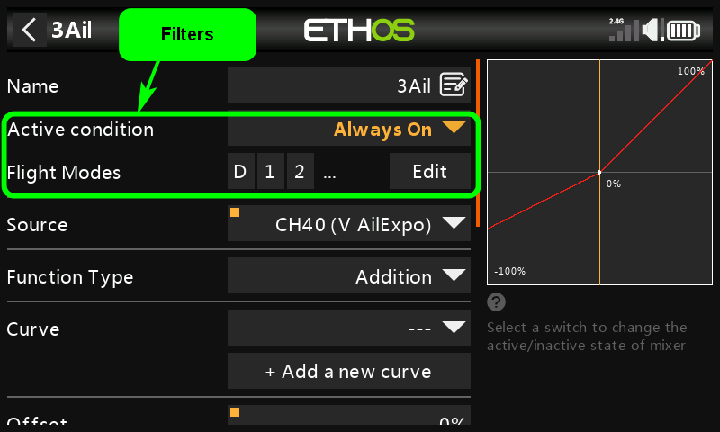
Mixer filters
The first filter is Active condition. This is a general purpose filter. For the mix to be active, the condition must be satisfied. A common use of Active condition is to enable/disable a mix using a switch. The default is 'always on'.
The second filter is Flight modes. Use this if you want a mix to be active in one or more flight modes only. The filter is simply a list of flight modes which you can tick. By default, all flight modes are included in the list.
That concludes our introduction to mixers. For details about the individual mixers, please see the Mixers Reference page.
How mixer values are aggregated
In this section, we'll see how channel values are calculated. Central to this process is the mixer list:
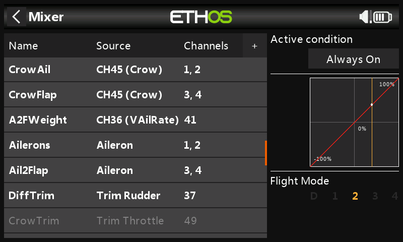
The mixer list. Each line shows the name, source, and one or more output channels
OK, so get ready because we're going to drill down into the detail!
At the start of each processing cycle, Ethos resets all channel values to zero. Next, Ethos steps through the mixer list, starting at the top. For each mix, the output(s) are calculated and added to the corresponding channel. When all the mixers have been processed, each channel value will be the aggregate of all its contributing mixes.
If a channel has no contributing mixers, it will have a value of zero corresponding to nominal servo centre.
Outputs layer
Once the channel values have been calculated, they're passed to the Outputs layer.
The Outputs layer is the glue which maps your ideal mixer design to the imperfect geometry of the real model. Put another way, it's where you set the operating limits of your servos, and compensate for differences between the left and right sides.
Technically, the Outputs layer performs two main tasks: first it clips the channel values so they lie between +/-100%. Second, it converts the results to PWM values representing actual servo deflections.
Let's look at each process:
Channel clipping
If a channel is driven by more than one mixer, it's possible that aggressive stick movements would cause the aggregated mixer value to exceed nominal limits of +/-100%. A common example is a V-tail setup, where each V-tail channel is driven by both rudder and elevator controls.
To prevent channel values exceeding the 100% limits, Ethos clips (limits) them so that they lie between −100% and +100%. A channel which is clipped in this way is 'saturated'. When saturation occurs, the servo will stop dead. This may or may not be a problem depending on how you use the controls.
If saturation is a problem, it can be mitigated or eliminated by reducing the weight of the constituent mixers. For example, with a V-tail setup, reduce the weight of the elevator and rudder mixes so that their sum is ≤100%.
By now, you're probably asking: what do these % channel values actually mean? They are in effect the percentage of available travel on that channel. In the next section, we'll see how to define that range by mapping channel values to PWM commands.
Mapping of channel values to PWM commands
In the final step, Ethos maps the (clipped) channel values to PWM values representing actual servo deflections.
The mapping is defined in the Outputs menu.
- Min defines the PWM value corresponding to an incoming channel value of −100%.
- Max defines the PWM value corresponding to an incoming channel value of +100%.
- Subtrim defines the PWM value corresponding to an incoming channel value of zero.
- Direction sets normal/reversed output.
Note that Min, Max and Subtrim effectively define a three-point curve.
Since the channel values are clipped to +/−100%, the values of Min and Max define the limits of travel.
PWM units
Although PWM values are normally shown in μs (microseconds), they are entered as percentages of standard servo travel. The relationship between the units is as follows:
- −150% = 732 μs
- −100% = 988 μs
- 0% = 1500 μs
- 100% = 2012 μs
- 150% = 2268 μs
In practice, you don't need to worry too much about their values, as you'll make the adjustments visually.
The outputs monitor
The outputs monitor screen is a useful aid for debugging the mixers and outputs. Each channel is displayed with an orange and a green bar.
- Green bar. This is the aggregated mixer value from the Mixers layer. This is useful for checking the mixer logic.
- Orange bar. This represents the final PWM value after Outputs processing. The microseconds are shown above and right of the bar. Use it to check how far your servos are being driven.
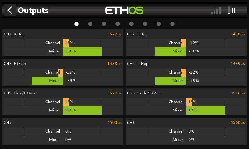
The outputs menu, showing the aggregated mixer values (green bars) and the final output/PWM values(orange). Note PWM value in μs above channel bar
Mixer functions (advanced topic!)
That's all the main items covered... but here's a little extra before we finish. It's about mixer functions and it's quite advanced; you only need to read this if you intend using free mixes. Here goes …
Each mix has a function associated, for updating the channel values during the main processing loop. For all mixers except Freemix, the only function available is add, and cannot be changed (in fact the option is hidden). Since addition is not order-sensitive, you can position your mixers at any convenient position in the mixer list.
Things are more interesting with mixers of type 'FreeMix'. In addition to the add function, these mixers also offer replace, multiply and lock — and the mixer order is significant for these. Here's how the functions work:
- Add: the mixer outputs are added to the channel values.
- Multiply: the channel values are multiplied by the mixer outputs, and the results becomes the new channel values.
- Replace: the channel values are replaced by the mixer outputs.
- Lock: same as 'replace, except that subsequent mixes affecting the outputs are ignored.
Here's a rather artificial example for illustration only: a setup with four free mixes and various functions. The inputs are not important in this example, we're only interested in the outputs:
Mix_1: Function=Add, Out_1=>(CH1, CH2)
Mix_2: Function=Multiply, Out_2=>(CH2, CH3)
Mix_3: Function=Replace, Out_3=>(CH3)
Mix_4: Function=Add, Out_4=>(CH3)
Let's see what happens to the channel totals as Ethos steps through the mixer list:
| Step | CH1 | CH2 | CH3 | Notes |
| [Initial] | 0 | 0 | 0 | Ethos initialises channels to zero |
| Mix_1 | Out_1 | Out_1 | 0 | Mix_1 output is added to CH1, CH2. |
| Mix_2 | Out_1 | Out_1*Out_2 | 0*Out_2 = 0 | Mix_2 output multiplies previous CH2, CH3 |
| Mix_3 | Out_1 | Out_1*Out_2 | Out_3 | Mix_3 output replaces previous CH3 |
| Mix_4 | Out_1 | Out_1*Out_2 | Out_3+Out_4 | Mix_4 output is added to previous CH3 |
Uses for Multiply and Replace
A full treatment is beyond the scope of this article, but in a nutshell:
- Multiply may be used to implement adjustable mixes, where the target mix is multiplied by the adjuster mix.
- Replace is handy for the motor channel, where you may have an idle mix (source = MIN), overridden by a throttle mix when the motor is armed.
Summary
Okay, so let's summarise the processing during each cycle.
- Inputs (sticks, knobs, sliders etc.) are read.
- Channels are initialised to zero (corresponding to centre).
- The mixers are processed, and their outputs added to the corresponding channel.
- The channel values are passed to the Outputs stage where they are clipped, then mapped to PWM values according to Min/Max/Subtrim.
- The PWM values are passed to the RF module for transmission.