Safe motor arming system
Introduction to arming
With the high power output of modern electric motors, safety has never been of greater importance, yet our radios provide only weak protection.
In this article, I describe a simple framework for a safe motor arming system. The technique is very flexible and well proven in my E-Soar Plus templates.
By the end of the article, you should be able to design and construct your own customised system. You'll also learn how to use the powerful Sticky logical switch.
Definitions of terms
First let's define some commonly used terms:
- Arming: an action which allows the motor to run.
- Disarming: an action which prevents the motor from running, and stops it if already running. (Killing is a special case, whereby the motor is disarmed immediately and unconditionally.)
- Gesture: a user action which involves moving switches and/or sticks in a particular manner.
What is a 'safe' arming system?
So what do we mean by a 'safe' system? I'll throw out four key conditions which must be satisfied:
- The motor must be guaranteed disarmed at startup, without the need for switch checks.
- A user action, or sequence of actions, is required in order to arm
- The throttle must be in the idle position before arming can be accomplished
- While the motor is armed, it will always respond to throttle commands until it's disarmed (for predictability)
Implementation overview
An arming system consists conceptually of two parts.
The first part is the arming switch. From the point of view of the motor, the arming system acts like a switch. When the switch is 'On', the motor is armed and allowed to run. 'Off' means it's disarmed and stopped. In reality, our switch will be a sticky logical switch as this provides much more flexibility than a real switch.
The second part consists of two mixes, one to control the motor using the throttle, and the other to force it stopped. The arming switch is used to switch between these two mixes.
The Sticky logical switch
For the arming logic, we will use a Sticky logical switch. Here's a quick tutorial.
A Sticky acts like a physical on/off switch, except that the 'on' and 'off' actions can be customised. The Sticky takes two parameters, V1 and V2. These define the on and off triggers. Each trigger may be a physical or logical switch.
- When V1 transitions to On, the sticky flips to On
- When V2 transitions to On, the sticky flips to Off
A simple example, where a Sticky mimics a 2-position switch:
With the example above, moving SF down flips LS1 true. Moving it up flips LS1 false. In effect, LS1 is equivalent to 'SF↓'. Not very useful!
Things get more interesting when triggers are themselves logical switches, as this allows us to flip the sticky using gestures like 'stick in corner + pull momentary'. But before we explore further, let's explore another benefit of using a sticky...
Arming without switch checks
One of the cool things about a Sticky switch is that it's off (false) by default. This means that the motor is guaranteed to be safe until the 'on' gesture is carried out - without the need for switch checks. (Avoiding switch checks is a safety benefit since switch checks are easily bypassed.)
There's one condition which you, the programmer, should observe when programmig the sticky switch: namely, the arming condition (V1 parameter) must not be a regular 2- or 3-p switch. Why? Because if - perhaps by mistake - the switch is in the On position at startup, the sticky switch will immediately transition to On and the motor will be armed - something we specifically want to avoid.
Instead, V1 should be either a momentary switch, or a logical switch representing a complex gesture. That way, the motor only will be armed when you decide!
Example 1: arming using a complex gesture
Okay, we're now ready to create our first 'safe' arming system. First, we need to specifiy the degree of safety needed as these will guide our choices of gesture for arming and disarming. It's up to you to decide on the balance between security and convenience, but for our first example let's set the following goals:
- Arming should be difficult so it can't be done by accident
- Disarming should be easy - but not too easy
To this end, we'll use a 3-step gesture for arming, and a simple gesture for disarming.
Arming:
- Move throttle stick to idle
- Move elevator stick fully back
- Pull momentary switch briefly
Disarming:
- Pull and hold momentary switch SH for 2 secs
The screenshot below shows the logical switch scheme as they're entered in Companion.
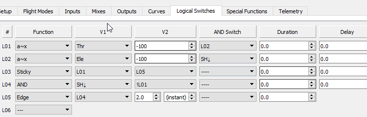
Logical switch scheme
How it works:
- L3 is the Sticky switch for arming and disarming the motor. L1 is the arming gesture, and L5 is the disarm gesture.
- L1 is the arming gesture: throttle to idle + elevator fully back + pull SH.
- L5 is the disarm gesture:
- L5 goes True briefly, after L4 has been true for 2 seconds.
- L4 is true while SH is pulled, but not while arming ('!L1')
Note that 'Thr' and 'Ele' refer to sticks (not inputs). In the mixer menu, inputs are prefixed with 'I', sticks have no prefix.
Example 2: arming via 'smart' 2-position switch
Some F5J competition pilots like to use a simple 2-position switch for arming. However, there's a problem with using a regular switch: we cannot guarantee that it's in the 'Off' position (disarmed) at switch on. That disqualifies it from being 'safe'.
However, there's a trick that we can apply so that the switch reports 'Off' at startup, regardless of the actual position. To do this, we put the physical switch behind a Sticky logical switch, with further logic for the V1 (True) parameter. Here's an example showing how 2-position SF can be made smart:
L2: Edge SF↑ [0, infinite]
L3: Sticky (L2, SF↑) -- arming switch
- The arming switch L3 is False (disarmed) at startup. It'll go True (armed) when L2 triggers.
- L2 triggers a brief True pulse when SF ceases to be Off, in other words, when it transitions from Off to On.
The key here is the word 'transition'. If SF is On at startup, it must be toggled Off-to-On in order to arm. [Credit to Jesper Frickmann for this snippet.]
Note: In practice, a condition would be added to L2 for the throttle to be at idle.
Integrating the arming switch
We've seen how to program an arming switch. In this section, we learn how to apply it to the motor channel. Two mixers are needed, one to force the motor to idle (the default condition), and a second 'Replace' mix to pass control to the throttle stick when the system is armed.
In the example below, CH7 is the motor channel, and L3 is the sticky arming switch.
CH7:Motor
Source=MAX Weight (−100%)
Source=Thr Weight (+100%) Switch (L3) Multiplex=REPLACE
How it works:
- The first mix ('MAX') sets the motor to motor off. This mix is always active. The weight of −100% ensures that the ESC receives a low PWM value, which is the convention for 'motor off'.
- The second mix ('Thr') passes control of the motor to the throttle stick. This mix is only active when the motor is armed (L3 is true). Note that the 'Multiplex' option is set to 'Replace', so that when active it overrides (instead of being added) to the first mix.
Notes:
- To reverse the throttle stick (so idle is fully forward), change the weight to -100% in the second mix line.
- In the Outputs menu, Min, Max and Subtrim should be set to their default values (-100%, +100% and zero respectively).
The Override special function - not!
Some pilots use the 'Channel override' special function to turn off the motor. However it has some major drawbacks:
- It cannot be part of an integrated arming system
- It is not possible to determine if the motor is running via a logical switch since Override bypasses the logic
- It's difficult to debug since the logic is split between two menus
I don't recommend this approach. (Interestingly FrSky agree, since their Ethos operating system - while similar in many ways to EdgeTX - does not provide an override function).
Flight mode considerations
So far we've made no mention of flight modes, and that's for a simple reason: the arming system should be independent of flight mode. So, if you have different flight modes for the power-on and power-off phase, your arming system logic does not need to take this into account.
Conversely, any 'power-on' flight modes should not be triggered by the arming system. Instead, define a logical switch to determine if the motor is actually running, and use that switch to trigger the power-on flight mode.
Logical switches
Lxx: CH7(motor) > -100 -- true if motor running
Flight modes
FM:Power switch=Lxx
Download
Arming/kill switch demo
Requirements
- For OpenTX 2.2 and above
Files
- MotorArmKill.otx (arming/kill switch operating on CH3)
Safety first!
- Use the channel monitor to test operation before connecting up the motor
- Remove the propellor for first tests
- Test, test and test again
- Remember to set the failsafe, so motor goes to idle on loss of signal