How to make in-flight adjusters
Introduction
Trimming out a new model can be a long process, involving lots of small adjustments to diff, mixing, and so on. The traditional procedure is to fly, land, and adjust, and it can take dozens of cycles to achieve that perfect setup.
But hey, this is EdgeTX... so why not make adjustments whilst actually flying the model!? Not only is it better for the model (since fewer landings are required), it means you can compare settings instantly. In short, your model will fly better, sooner...
In this article I'll describe how you can do this, using custom in-flight adjusters. These are knobs, sliders or trims which are programmed to act like volume controls. They can adjust a mix, diff, expo... or anything you like. As an example, the graphic below shows the in-flight adjusters on my F3F setup:
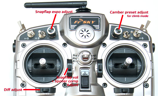
In-flight adjusters on author's F3F setup
The volume control
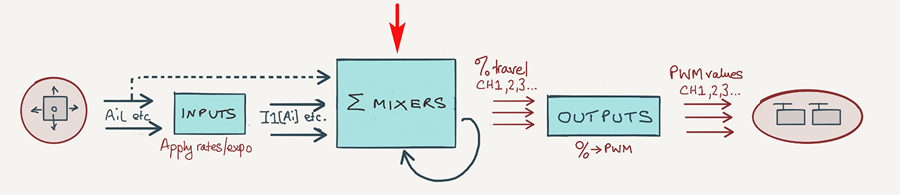
Various strategies exist for implementing in-flight adjusters, however all of them are based on the concept of a volume control.
A volume control consists of two parts: a physical control which you move with your finger; and a mixer which converts the position of the control to a percentage value. By applying the %age value to the output of another mixer, we have our in-flight adjuster. It really is that simple - in principle at least.
In practice a little 'scaffolding' code is required to interface the adjuster with the mixer we want to adjust. But we'll come to that later. First, let's make the basic building block: a simple volume control.
Creating a simple volume control
Our first volume is based on knob S1. It outputs a value between 0% and 100% depending on the position.
To do this, create a mixer with source=S1, weight=50% and offset=50%:
CH10
Source=S1, Weight=50, Offset=50
How does it work? Recall that the output is calculated according to this formula:
Output = (source * weight) + offset
Let's see what happens if we set weight=50% and offset=50%.
- With knob S1 fully anticlockwise, src=−100%, so output = 0%.
- With S1 fully clockwise, src=100%, so output=100%
In other words, the output of the mixer line varies between of 0% and 100% - just what we want!
We'll use this volume control an example later on. Next, let's see how to alter the range of adjustment.
Change the range of adjustment
The volume control above provides an adjustment range of 0% - 100%. But what if a different range is required? For example, for adjusting aileron diff, the range should be something like 10 - 70%.
In this case, we must determine weight and offset by calculation. Here's now:
- Determine the minimum and maximum %ages.
- Apply the formula weight = (max−min)/2
- Apply the formula offset = (min + max)/2
For example, to create a volume control with range 10% to 70%:
- weight = 60/2 = 30
- offset = (70 + 10)/2 = 80/2 = 40
CH10:vol control 10% to 70%
Source=S1 weightt=30 offset=40
Later on, we'll use this volume control in a diff adjuster.
Reversing the volume control
To reverse the direction of the volume control, simply invert the sign of weight:
CH10:vol control 70% to 10%
Src=S1 wt=−30 offset=40
Example: snapflap adjuster
Let's look at some complete real life examples. We'll start with a simple snapflap adjuster. Snapflap is just another name for an elevator-to-flap mix: as you move the elevator stick, the flaps rise or fall.
We'll start by creating a simple snapflap mix with a maximum weight of 25%.
CH4:flap 1
Src=Elevator wt=25 trim=No
Next, make a volume control with a range of 0% - 100%.
CH10:volume -- vol control 0% to 100%
Src=S1 Wt=50 Offset=50
Next, multiply the snapflap mix by the volume. To do this, add a second mixer line, setting the source to the volume control channel.
CH4:flap_1
Src=Elevator wt=25 trim=No
Src=CH10:volume wt=100% Multiplex= MULT
The MULT directive means "multiply the output of CH10:volume line with the result of the lines above". There's only one line above, namely the snapflap mix. The result is assigned to the flap channel (CH4). Snapflap will now vary between 0% and 25%, depending on S1.
Example: aileron differential adjuster
Let's move on to something slightly more complex - an adjuster for aileron differential. We use S1 as the volume control, this time with a range of 10% to 70%.
CH10:volume -- vol control 10% to 70%
Src=S1 wt=30 offset=40
The next task is to build some scaffolding code, to link the diff value to CH10.
Now here's a small problem: OpenTx/EdgeTX do not allow diff to be linked directly to CH10. However, diff can be set via a global variable (GVAR). So we do it in two stages. First we use the volume control to update GV1, then we use GV1 to update diff.
So, go to the Special Functions menu and add an 'Adjust GV' line. Set it so that GV1 is the target to be updated, with CH10:volume is the source.
SF1 -- stores volume % in GV1
Switch=ON Function=Adjust GV1 Source=CH10:Vol Enable=On
GV1 is now bound to CH10:Volume.
Finally, we assign GV1 to Diff:
CH1:aileron1
Src=Aileron Wt=100% Diff=GV1
Aileron differential suppression
With F3X sailplanes, applying crow brakes reduces roll response. One way of counteracting this is by suppressing aileron differential. As crow is deployed, any aileron differential is reduced to zero. This increases the effect of the downgoing aileron, which helps to restore roll response. To summarise:
- with crow off (Thr=+100%), diff = value as set in the aileron channels
- with full crow (Thr=−100%) diff = zero
In effect, the crow position is acting as a volume control! Although it's not a manual adjustment, it works the same way. So we can build on the previous example, just adding a second volume control based on the crow stick (Thr).
So our crow-based volume control looks like this:
The mixer stack for the combined volume control (CH10) is therefore:
CH10: vol control + diff suppression
Src=S1 wt=30 offset=40 -- S1 adjuster
Src=Thr wt=50 offset=50 Trim=no Multiplex=MULT -- diff suppression
Note the MULT directive in the last line, for multiplying the two volume controls.
Finally, some code is needed to set the diff value - this the same as for the diff adjuster in the previous section.
Using trims as adjusters
Spare Trims can be used as adjusters, just like sticks and knobs.
CH10:vol control 10% to 70%
Src=TrmR wt=30 offset=40
Trims are flight mode aware
Using a trim as an adjuster has another benefit: the adjuster will be flight-mode aware. In other words, adjustments are stored independently for each flight mode.
This gives you the freedom to repurpose a trim lever in multiple flight modes. For example on my F3F template, the throttle trim adjusts either (a) spoiler compensation or (b) snapflap volume, depending on the flight mode.
A closer look at the 'MULT' operator
Mixers normally use the ADD operator, which is not order sensitive. However the MULT operator is order sensitive. A MULT mix will multiply itself with the result of all the lines above. Get the mixer order wrong and you can introduce a bug. For example, take our snapflap example:
CH4:flap
Src=Elevator wt=25 trim=No -- snapflap mix
Src=CH10 Multiplex= MULT -- volume control
Suppose we add a camber mix controlled by S1. First, we'll place the mix at the top of the stack:
CH4:flap
Src=LS wt=100% -- camber
Src=Elevator wt=25 trim=No -- snapflap
Src=CH10 Multiplex= MULT -- volume control
Immediately we have a problem: The MULT directive acts on lines above it, so it will also act on the new camber mix.
The correct location for the new camber mix is after the volume control. That way, the camber mix will be added without adjustment.
CH4:flap servo
Src=Elevator wt=25 trim=No -- snapflap
Src=CH10 Multiplex= MULT -- volume control
Src=LS wt=100% -- camber
Using a curve to set the adjustment range
As we saw with the volume control for Diff, determining the correct wt and offset may involve some calculation. A more direct approach is to use a curve.
Let's compare the two approaches. The aim is to set a volume range of 10% to 70%. First, the original method using offset and wt:
CH10:vol control 10% to 70%
Src=S1 wt=30 offset=40
Here's the alternative method, using Curve 1 to define the range:
Curve 1
2 points: 10%, 70%
CH10: vol control 10% to 70%
Src=S1 Curve/Differential = "Curve 1"
The benefit of the curves approach is that it's more explicit. On the other hand, the work is split between two screens, making it arguably more difficult to maintain. Whichever method you use will come down to personal preference.
Applications for adjusters
Applications for in-flight adjusters include:
- D/R, Expo
- Snapflap volume
- Spoiler compensation trim
- Aileron differential suppression
- Camber
- Snapflap expo (though the scaffolding for this is somewhat more complicated!!)
- Anything else you care to think of!
Whatever type of model you fly, there is bound to be a use for in flight adjusters, so get experimenting!
Happy flying :-)