
Cascading mixers
What is cascading?
Cascading (or chaining) is a way of linking channels, so that the output of a channel is fed to one or more mixers in other channels. This technique reduces duplication and offers a single point of adjustment.
In the example below, CH10 provides a camber function to flap channels CH1 and CH2. The camber rate is set in just one place (CH10).:
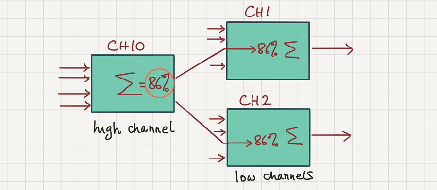
Cascading can also used to break down a complex mixing scheme into simpler chunks which can be individually tested.
Weights are multiplied cumulatively
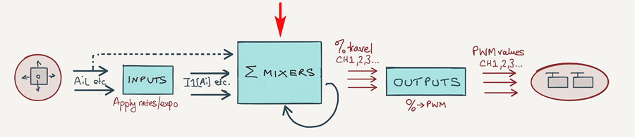
Cascading works by feeding the output of a channel to another mix. There's nothing special about this - the source is treated just like any other source, in other words weights and offets are applied just as if the input was a stick instead of a channel. This means that weights are applied cumulative through the cascade.
Consider an example: CH1 is driven by knob S1, and the output of CH1 is cascaded to CH2:-
CH1
Source=S1 Weight=80
CH2
Source=CH1, Weight=25
The output of CH2 varies, as CH1 varies, as S1 varies.
The weights cascade by multiplication, so
CH2 = CH1 x 25% = S1 x 80% x 25% = S1 x 20%.
So, as S1 is rotated between its end stops:
- The output of CH1 will vary between -80 and +80
- The output of CH2 will vary between -20 and +20
The MULT operator
Though not strictly part of cascading, some of the examples below use the MULT (Multiply) mixer operator. The MULT operator is used to multiply mixes within the same channel.
CH1
Source=RS, Weight=100
Source=S1, Weight=100, multiplex=MULT
In the example, CH1 = (100% x RS) x (100% x S1) = RS x S1
Snapflap example
Okay, so let's look at another example in more detail. We'll implement an elevator to flap mix, also known as 'snapflap'. And we'll have a look at both the traditional and cascading approaches to the problem.
Snapflap the old way
First, here's the 'brute force' approach without cascading:
CH3:right flap
Source=Ele, weight=35
...
CH4:left flap
Source=Ele, weight=35
...
In order to adjust the amount of snapflap, two identical adjustments are needed, one in each channel.
Snapflap using a cascading mix
Let's modify the code. We'll isolate the snapflap mix in, say, CH10, and cascade its output to the individual flap servos:
CH10:snapflap
Source=Ele, weight=35
CH3:right flap
Source=CH10, weight=100
CH4:left flap
Source=CH10, weight=100
Woohoo! CH10 now provides a single point of adjustment for both flaps.
It's good practice to reset the weights in CH3 and CH4 to 100% (remember that weights are multiplied cumulatively as OpenTx progresses through the cascade).
Extending snapflap to the ailerons
On a 4-servo wing, you'll want snapflap to apply all four surfaces. So let's also cascade the snapflap value (CH10) to the ailerons:
CH10:snapflap
Source=Ele, Weight=35
CH1:right aileron
Source=CH10, Weight=100
CH2:left aileron
Source=CH10, Weight=100
CH3:right flap
Source=CH10, Weight=100
CH4:left flap
Source=CH10, Weight=100
This'll work, but there's a problem: CH10 controls both flaps and ailerons without distinction. In practice the linkages for flaps will be quite different to those of ailerons. To cater for this, we'll set up a dedicated high mix for the ailerons, in CH11:
CH10:snapflap -> flaps
Source=Ele, Weight=35
CH11:snapflap -> ailerons
Source=Ele, Weight=15
CH1:right aileron
Source=CH11, Weight=100
CH2:left aileron
Source=CH11, Weight=100
CH3:right flap
Source=CH10, Weight=100
CH4:left flap
Source=CH10, Weight=100
So now,
- To adjust the flaps, we alter the weight in CH10.
- To adjust the ailerons, we alter the weight in CH11.
We can adjust CH10 and CH11 to achieve the desired relative movement between flaps and ailerons.
Adding a global snapflap adjuster
Say we want to adjust the overall snapflap whilst flying the model. We can do this by creating a volume control, and applying it to CH10 and CH11.
We start by making a volume control based on knob S1, with range 0% to 100%:
CH20:global snapflap adjuster
Source=S1, Weight=50, offset=50
The output of CH20 varies from 0 to 100% as S1 is rotated clockwise. To use this as a global adjuster, we cascade the output to CH10 and CH11, using the MULT operator:
CH20:global snapflap adjuster
Source=S1, Weight=50, offset=50
CH10:snapflap->flaps
Source=Ele, Weight=35
MULT: Source=CH20
CH11:snapflap->ailerons
Source=Ele, Weight=15
MULT: Source=CH20
CH1:right aileron
Source=CH11, Weight=100
CH2:left aileron
Source=CH11, Weight=100
CH3:right flap
Source=CH10, Weight=100
CH4:left flap
Source=CH10, Weight=100
The MULT operator multiplies the global adjustment (from CH20) with the local adjustments of 35% (flaps) and 15% (ailerons). (Without the MULT operator, the local and global adjustments would be ADDed, which is of course not what we want).
Let's dig a little deeper: taking CH10, which controls the snapflap mix to the flaps:
CH10 = CH20 x Ele x 35% = Ele x S1{0−100%} x 35%.
Rotating the global adjuster varies the snapflap mix between 0% and 35%. Similarly the range for the ailerons is 0-15%.
So now, we use the local adjustments to set the relative travels for aileron and flaps, and the global adjuster S1 to tune both together.
Floating the MULT upwards
A variation is to move the elevator input to the global adjuster line:
CH20:global snapflap adjuster
Source=S1, Weight=50, offset=50
MULT: Source=Ele, Weight=100
CH10:flaps
Source=CH20, Weight=35
CH11:ailerons
Source=CH20, Weight=15
CH1:right aileron
Source=CH11, Weight=100
CH2:left aileron
Source=CH11, Weight=100
CH3:right flap
Source=CH10, Weight=100
CH4:left flap
Source=CH10, Weight=100
The result is exactly the same as before, but isolating the MULT line at the top layer will make it easier when we add extra mixes.
Extending the mixers
Suppose we want to add a camber mix, controlled by slider LS. Ailerons and flaps will be affected, and we'll have a global adjuster (S2).
We can do this using similar code to snapflap:
CH21:global camber adjuster
Source=S2, Weight=50, offset=50
MULT: Source=LS, Weight=100
CH20:global snapflap adjuster
Source=S1, Weight=50, offset=50
MULT Source=Ele, Weight=100
CH10:flap mixes
Source=CH21, Weight=20 -- camber
Source=CH20, Weight=35 -- snapflap
CH11:aileron mixes
Source=CH21, Weight=7 -- camber
Source=CH20, Weight=15 -- snapflap
CH1:right aileron
Source=CH11, Weight=100
CH2:left aileron
Source=CH11, Weight=100
CH3:right flap
Source=CH10, Weight=100
CH4:left flap
Source=CH10, Weight=100
So now CH10 aggregates the camber and snapflap mixes. Note the small number of changes needed!
In practice, snapflap and camber will be active in different flight modes. We can achieve this by applying a flight mode filter as follows:
CH21:global camber adjuster
Source=S2, Weight=50, offset=50, flightmode='thermal'
MULT: Source=LS, Weight=100
CH20:global snapflap adjuster
Source=S1, Weight=50, offset=50, flightmode='speed'
MULT: Source=Ele, Weight=100
...
...
It's fairly clear how the above works if thermal mode is selected, but maybe not so clear in other flight modes, so let's break it down...
In flight modes other than thermal, then CH21 is equivalent to:
CH21:global camber adjuster
MULT: Source=LS, Weight=100
So we now have the equaivalent of a single MULT mix. MULT mixes are applied to the result of all the mixers above it. In this case there are no mixes above, so the result of all the lines above is zero, and the value of CH21 is therefore zero. So, in modes other than thermal, camber will be zero - which is what we want.
Combining with GVARs
One final tweak is to put the local adjustments (CH10, CH11) into a GVAR.
...
CH10:flaps
Source=CH20, Weight=GV1
CH11:ailerons
Source=CH20, Weight=GV2
...
This offers a couple of benefits:
- GVARs are flight mode aware, so you can have different local adjustments depending on the flight mode - without the need for additional mixer lines.
- It moves the adjustments from the Mixers menu to the more user-friendly GVARs menu.
Limitations of cascading
There are some rules and limitations to observe when cascading.
In CH10 and CH11 above, the camber and snapflap inputs have the same 'directionality': they move control surfaces in a similar way.
Suppose we wanted to combine an aileron function ('flapperon'). Aileron has a different directionality to camber and snapflap, so we cannot simply add it to CH10 and CH11. Instead, we would need to define additional aggregator channels. Another complicating factor is differential - this must be applied at the level of individual servos.
For more insight, I would recommend having a look at my F3X templates, in particular the XLS reference documentation which contains both the schema and annotations.
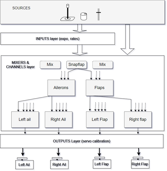
Hierarchical design
In the structure which we've developed in this article, you'll note that there three distinct layers:
- Top layer: global adjusters CH20 and CH21. They're cascaded to the ...
- Middle layer: local adjusters CH10, CH11. These affect ailerons and flaps, in pairs. The outputs are cascaded to...
- Servo layer ... CH1,2,3 & 4 , the individual servo channels.
Cascading can be extended to other mixes such as reflex and crow brakes. The result is a hierarchy of mixers, fed by sources and inputs, with a calibration layer to deal with linkage differences. This type of schema is economical with mixers and is ideal for F3X models.
Summary
Let's summarise what's been achieved by employing cascading mixers.
- We have isolated the common mixer code, reducing duplicate mixers
- Each mix is adjustable via a single menu point, with perfect tracking guaranteed (assuming the servos are calibrated)
- We have made it easy to extend the mixing